Preface: I have seen & read many on the internet refer to the 1/2/BOTH as "Maine Sail's preferred method".. Let me be clear on this point; this is not my preferred method it is simply a method.. I am only posting options in order to show how the 1/2/BOTH can be used in an easier and often less confusing manner. Many boat owners don't have the luxury of starting from scratch and the existing switch can usually be re-used/re-purposed easier, and in a less costly way, than converting to a multiple switch configuration..
Basic Design Principles For Battery Switching:
#1 Bank Isolation - The ability to isolate a battery bank from both loads and charge sources in the event of a bank or battery failure.
#2 Cross Connection Use - The ability to use either on-board battery bank as the sole use bank, meaning it serves as starting and house load bank in an emergency, This design should always include #1.
The 1/BOTH/2/OFF Switch
Over the years most all boat builders, of both sail and power, have installed the simple and redundant 1/BOTH/2/OFF switch. The switch, I believe, has gotten an undeserved bad rap over the years. Why? It's really not necessarily due to the switch itself but rather due to the way most builders install them, and the way many boaters have used them.
Despite the bum rap, the 1/BOTH/2/OFF switch remains a versatile & redundant single-switch battery selector. Surprisingly, even today, they are still the #1 selling multi-bank battery switch made other than the simple ON/OFF. They offer more redundancy and isolation than just about any other easy to use configuration. The "easy to use" part is arguably debatable, hence this post. It should be "easy" but lack of a complete understanding leaves many in a lurch.
Builder Blunders?
The 1/BOTH/2/OFF switch, as wired by builders, becomes a Bank Selection and Charge Directing switch. What, huh? What this means is, what ever position you have the switch set to is where your on-board energy comes from and where the engines alternator charges to.
What Bank Selection and Charge Directing means:
Switch Set to;
Bank 1 = DC loads are drawn from bank #1 and alternator charging goes to bank #1
Bank 2 = DC loads are drawn from bank #2 and alternator charging goes to bank #2
BOTH = DC loads are drawn from BOTH banks and alternator charging goes to BOTH banks
OFF = Both battery banks are isolated/OFF
Note: Even when set to OFF a bilge pump, propane sniffer, stereo memory or VHF may still be direct wired to the house bank so the vessel may still have "live" 12V wires..
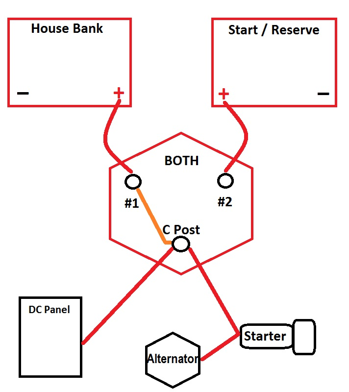
Most builders simply wire the alternator circuit back through the starter feed wire to the "C" or common post of the battery switch. This "C" post is the one that gets energized when you flip to 1, 2 or BOTH and is isolated or disconnected when you switch to OFF. This wiring method is CHEAP, easy and gives you lots of options but leaves owners with lots of room for human error and misunderstanding.
This factory wiring works simply and allows you to choose which bank you are charging or drawing from by selecting that bank on the switch. Set it to bank #1 and bank #1 gets charged/discharged. Set it to bank #2 and bank #2 gets charged/discharged. Set it to BOTH and both banks get charged/discharged. Forget to charge bank #1 and bank #1 never gets charged etc. etc.. Leave it on BOTH and run the banks dead and now you're SOL... This is called the Human Error Factor (HEF)..
In this drawing the orange line is showing the switch connecting the house bank to the "loads" via the "C" post of the battery switch. You can visually see the path the alternator takes to get back to the battery bank. The orange line represents the switch position.
Owner Blunders?
So why is this factory wiring bad? It's not necessarily bad if you understand your system and how to use it.
HEF / Human Error Factor Modes;
Blown Alternator Diodes - The big blunders happen when you or a crew mate tries to switch to another bank and you or they pass the battery switch through the OFF position with the engine running and charging the batteries. Passing through OFF, or disconnecting the "load" from the alternator, can cause a massive voltage spike as the "load" or battery bank is disconnected from an alternator while it is trying to charge it and POP goes the diodes.....
Picture, if you will, a bunch of speed skaters in a race. They are moving at full sprint when all off a sudden a Jersey Barrier falls from the sky onto the ice rink. The skaters all pile up and smash into the barrier and boom they are out of commission. This is similar to what happens in your alternator when you shut the battery switch off. All the "flow" piles up with no place to go causing a very fast voltage spike that blows out the diodes.
Damage to Sensitive Electronics - Unfortunately it's not just alternator diodes we need to be concerned with in a battery switch disconnect, though this is what most people notice first, that the alternator is no longer working. If you take a look at where your DC loads are connected this just happens to be the same place as the factory wired alternator. When the switch is opened and the alternator disconnected from the battery, and the alternator is pumping out 70A+, that energy has to go somewhere and it goes straight into your sensitive electronics in the form of a massive voltage transient. This "voltage transient" very often destroys the alternator diodes and also damages DC electronics. It is not uncommon for me to find multiple other items damaged when a customer comes to us for a "bad alternator" and the diagnosis is blown diodes...
In theory the voltage regulator would react and stop this voltage rise, they do limit voltage, but the spike happens too fast for the voltage regulator to react, we're talking damage occurring in microseconds. When you do this there is a high likelihood that the diodes in the alternator will blow and leave you with no alternator and potentially ruined DC electronics too.. This is bad, and the factory wiring does nothing to limit or protect against this. Some newer alternators, on late model engines, utilize "avalanche diodes". Avalanche diodes are more durable but most existing alternators do not have this feature.
The "I Must Set it to BOTH to Start the Motor" Mind Set:
This thinking is flawed and unnecessary, but at the same time it is backed up/supported in some owners minds because it acts as a Band-Aid for weak batteries or a poorly wired system.
A Band-Aid, or better put, BOTH, is only hiding or covering up for "issues" and does nothing to actually solve them. Despite this urban myth, and common boat owner misunderstanding, that you need to use BOTH for starting, you do not need to use BOTH to start your motor. If you do need BOTH to start your motor you have other issues that need to be fixed such as:
The use of BOTH to start you motor, or when charge directing, requires that you remember move the switch off of BOTH when you shut the motor off, or shortly after. Unless you need to be in BOTH for charge directing, there should be no other need for this position in a well operating system that's also properly wired.
Unnecessary switching can lead to blow diodes & massive voltage transients with an inadvertent pass though the OFF position.
The other possible scenario is that an owner has forgotten to switch off of BOTH and killed BOTH BANKS leaving no reserve battery to start the motor with. You'd be surprised how many calls we get each year for this exact issue.
The normal human tendency, when these "blunders" or HEF happens, is to blame the "stupid" 1/BOTH/2/OFF switch. The switch is like a gun, the gun did not pull the trigger the owner of the gun did. How is the gun stupid? It's not, but the owner might be. How is the switch "stupid" when the owner makes a mistake? It's not, it did exactly as it was set to do, but is still often blamed for owner ineptitude or owner HEF. This is the bad rap I referenced earlier.
HEF = Human Error Factor - Humans are perhaps the worst part of the 1/BOTH/2/OFF switch.
So how do you make the 1/BOTH/2/OFF better or more simple to use?
There is little dire need on a small sailboat, with small aux diesel, to need a dedicated starting battery or to use "BOTH" to start your motor. If you need "BOTH", as discussed above, then there is another issue not getting addressed. As always, there are some caveats to this.
Dedicated Starting Battery - A hard wired battery bank used only for starting purposes and nothing else, except for emergencies. It is connected directly to the starter motor when the switch is on.
On our boats, and many of my customers boats, we/they have started our engines, for a long, long time on our house banks as do thousands boaters who use the 1/BOTH/2/OFF switch. We still use the simple, often called "stupid" 1/BOTH/2/OFF switch. The difference is that we only ever use position #1 (HOUSE) and OFF. It is simply a USE SWITCH...
1/BOTH/2/OFF As a USE SWITCH:
We use our switch as a "USE SWITCH" in a SIMPLE ON/OFF scenario. That's it, ON & OFF, or more accurately #1 & OFF. We do not use it as a charge directing switch, or a start on BOTH or #2 then remember to move to #1 switch. It is basically an ON/OFF switch the way we use it. Simple, effective and you likely already have one..
When we use our 1/BOTH/2/OFF switch position #2 (reserve bank) and BOTH are for an emergency only. I don't tend to think in terms of a start and house I think in terms of a reserve and house when using this switch in this configuration. This is but ONE WAY to do this as you'll see further on.
Wiring Upgrades To The 1/BOTH/2/OFF
The 1/BOTH/2/OFF switch is a very useful device and there are a few small changes you can do that can make it even more fool proof. Most of what you need for a very simple and redundant system is already there, so there is little need to spend more money on new switches or drill yet more holes in your boat over what you likely already have. This is of course predicated on the fact that you are comfortable with the idea of not using a "dedicated" starting battery.
To make your 1/BOTH/2/OFF a "USE SWITCH" simply:
1- Make your house bank #1, or "primary"
2- Make the start/reserve battery #2 or "back up/secondary"
3- Install an Automatic Combining Relay (VSR) or an Echo Charger to charge bank #2.
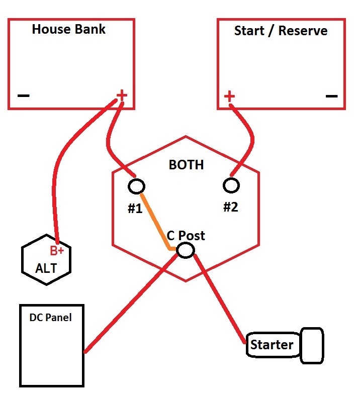
4- (Bonus Option) Feed alternator output directly to the house bank. If doing this it is best to install a battery compartment house bank isolation switch and create a charge "charge bus". If the bank fails you open the isolation switch and all charging now stays with the reserve battery.
Note: #2 as a secondary battery, for me, is always easy to remember but this is just a personal preference. It stems from the days of the Link 2000 & 2000R that necessitated the house bank be on #1 and start/reserve on #2.
Once you've re-wired you now have a USE switch and not a charge directing AND use switch. When you get to the boat simply switch to bank #1, start the motor and go. When you leave the boat simply switch to OFF. You'll use the house batteries for everything including starting. By doing this you'll only ever need to use position #1/House. Behind the scenes, and fully automatically, your emergency (start) bank will always be sufficiently charged via the battery combiner, which takes the place of manually switching to BOTH for charging both banks, or the Echo charger..
If and when the reserve bank is ever needed, and you've also upgraded to an Echo or ACR type charging device, the #2/reserve bank will be ready for an emergency and fully charged. The charging of the start/reserve bank can all be done behind the scenes and is automatic & seamless when you add an ACR/VSR or Echo type charger.
These small changes to convert the 1/BOTH/2/OFF to a USE switch greatly reduces the potential for HEF or memory lapses and makes needless switching, that can lead to blown alternator diodes, a thing of the past.
By wiring the alternator directly to the house bank it will ALWAYS see a load and you'll never need to worry about blowing the diodes by passing the switch through OFF. It is a good idea to install a "service switch" or a switch type circuit breaker, at the battery bank, so you can turn off the alternator feed if and when you're working on the engine. The alternator feed should also be fused as close to the bank as possible.
Echo Charger, Duo Charger or Combining Relay:
If installing an Echo Charger or Duo Charger it becomes necessary to route the alternator output directly to the House bank. This new alternator output wire should be sufficient to carry the entire alternator output with minimal voltage drop and should be fused within 7" of the house bank, or as close as you can. Remember a 3% voltage drop on 14.4V results in just 13.96V at the battery. The often repeated "size for a 3% voltage drop" really should not apply to charging systems, on deeply cycled banks, where the charge source is run for very short periods, if you want optimal charging performance. A 3% voltage drop in a charging system can slow charging and can lead to chronic under charging.
If installing an ACR (voltage sensitive combining relay) it is not entirely necessary to run the alt to the house bank. It is however a very good idea to do so if your house bank is significantly larger than your reserve bank as this can prevent relay cycling if the switch were set to the smaller bank.
Running the alternator output direct to the house bank serves the purpose of entirely preventing the frying of alternator diodes from turning the battery switch through OFF. Even with the engine running you can no longer "pass through OFF"..
What happens if I kill my house bank do I use BOTH then?
If you kill a bank don't fall into the trap of combining the dead bank with a perfectly good one by using the BOTH feature. Simply switch to the second fully charged reserve bank when or if you need to. Combining a good bank with a dead bank only bleeds off precious cranking amps from the good battery, as it tries to bring the voltage of the good battery to parity with the much larger house bank. It will not instantly kill the bank, as many on the net allude to, but there is no need for it, and it can be a bad habit to get into. If the bank has failed, and become an 8V or 10V bank vs. a 12V bank it can actually whack some potential from the bank needed for starting..
The use of BOTH in a dead battery situation is not necessary and can often be more detrimental than good, especially with disproportionately sized battery banks. The most important reason for not using BOTH is that you may not know the reason the house bank is dead . It could be due to an internal short thus creating a 10V battery, instead of a 12V battery.. Can BOTH work? Sure, but there is no need to do so and it can be detrimental. Just isolate the low bank and let the good battery start the motor.
Interestingly enough this past summer a customer lost his regulator and killed both of his battery banks. Dead as in 6.9V! Not paying as much attention as I should have I connected my jumper pack to his 440 Ah house bank of AGM batteries. By the time I got around to the engine switch all I got was "rrrr, rrruh, rrruh" then "click, click". The small jumper pack was not big enough to try and charge the large & very dead house & start banks and have enough left over to start the motor.
I came back the next day and connected the jumper pack directly to the starter battery only and disconnected the house bank. The Yanmar 3GM fired up. The larger your house bank the worse switching to BOTH can be on a small start battery. The jumper pack was able to start the motor via the dead start battery, but not when connected to the 440Ah house AGM bank.
Can my house bank really start my engine?
Yes, it can.. If you are practicing good battery management and never discharging the house bank below 50% state of charge you should always be able to start your engine just fine. This is providing that you have at least a two battery or more house bank and a typical small aux marine diesel or gas engine. If your house bank consists of a single group 24 battery at 50% state of charge you'd be better off to use a dedicated start battery.
Our boat had three group 31 batteries as a house bank. Even though they were "pseudo deep cycle" batteries they still produced a combined CA (cranking amp) capacity of well over 3000 amps at about 65 degrees F. Our single start/reserve battery, in comparison, only has about 1000 CA @ 65F. Our engine manufacturer wants to see about 400 cranking amps.
When you parallel batteries you increase the cranking amps.
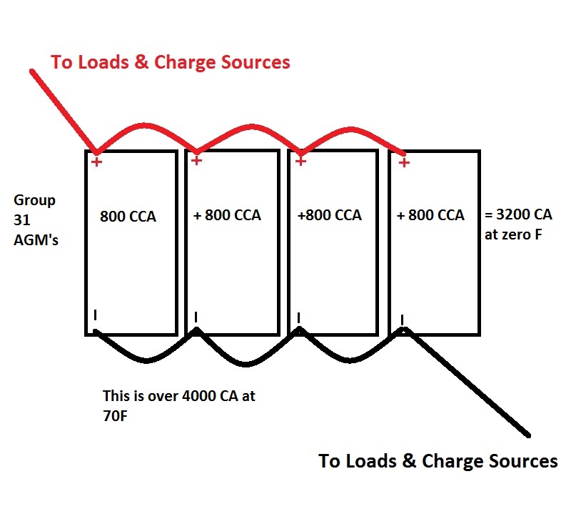
It takes VERY LITTLE from your bank to start a small diesel. In fact I can not even measure 0.1 Ah of consumption from a 240 Ah bank, using a Xantrex Link Pro when starting a 44HP four cylinder diesel.
Starting the engine requires very, very little from a battery, many folks over think this and believe it requires a lot more than it really does. Most house banks on cruising sailboats should be much more than necessary to start your engine.
This should show it well:
The 1/BOTH/2/OFF switch can be a great device, if wired & used appropriately & smartly. When wired in the fashion most builders do, and used the way many boaters do, it is less so and thus gets a bad rap.
The 1/BOTH/2/OFF switch retains all the original features & benefits yet looses the frying of diodes and the switching back and forth if you wire the alt direct to the house bank and use an ACR, Echo type charger to top off the start bank.
Redundancy & Isolation Features/Benefits:
* BOTH - Let's just say your ACR or Echo Charger failed, which could happen though is VERY rare, you can still use the ALL/BOTH feature to charge both banks from the alternator just as you always did, even if the alt is routed to the house bank.
* #1 bank can be used to start AND run house loads and can be 100% isolated from second bank.
* # 2 bank can be used to start AND run house loads and can be 100% isolated from second bank.
* You are not forced to combine a good battery with a bad battery bank in an emergency. This can be important especially if a battery bank developed a catastrophic internal fault. With a switch such as the Blue Sea Dual Circuit Plus switch you are required to combine battery banks in an emergency situation. With the 1/BOTH/2/OFF you can simply and completely isolate the bad bank and use the good one.
No Single Right Answer:
As always there is no one right way to wire banks, unless you do it dangerously, but on small boats it often makes little sense to ditch a perfectly good 1/BOTH/2/OFF and drill yet more holes in the boat when a simple re-wire of the existing switch will give you everything you need with simplicity and total redundancy should a combiner fail or a bank suffer a failure..
#1 Assign house bank to batt switch position #1
#2 Install reserve battery to position #2
#3 Wire alternator output directly to the house bank with sufficient size cable & fuse.
#4 Install ACR or Echo Charger between banks.
#5 Use boat in position #1 for starting AND house loads. Switch to OFF when you leave it's that simple.
So why would I want to wire my alt & other charge sources direct to the house bank??
#1 No more worries about fried diodes.
#2 Accurate voltage sensing, less connections & less chance of voltage drop over older factory wiring.
#3 If you use an Echo Charger, Duo Charger or other Battery to Battery type charger you'll need to do this anyway
#4 Allows the house bank voltage to come up to combine voltage before "combining" with the #2 bank. This prevents relay cycling when using an ACR/VSR type device with larger house banks.
When would I Not Wire The Alternator To The House Bank?
Scenario #1: You be best not to wire the alt directly to the house battery unless you have an isolation switch and charge bus. A battery compartment isolation switch on the battery side of the charge bus solves all this and keeps the charge sources with the bank in use..
Why?
If you wire directly to the house bank, bank #1, but do not have an isolation switch at the battery the house bank is still being charged when it has potentially failed. This is not a good practice and would require a wrench to isolate the failed bank from the charge sources. Course a wrench may mean teh alternator is now also removed so a charge bus is always a good idea! An isolation switch & charge bus is a very good idea for a 1/2/B as a use switch.
Follow me here, if you select bank #2 as your source, and the alt & external regulator are connected to bank #1, you will draw down bank two and not replenish it unless the ALL/BOTH function is selected during charging. In short, without an ACR or Echo type charger & a charge bus that can isolate charging from the house bank, I would not suggest wiring directly to the house bank and instead would leave it wired through the common post of the battery switch. As long as you are aware of the dreaded "passing through OFF" then you'll probably be plenty safe. Being educated about "fried diodes" often solves the issue for many of us.
With an ACR/Echo Charger you can still select bank 2 but it will still automatically be getting charged via the combiner or Echo even with the house bank being direct wired to the alternator. Of course this leaves you potentially charging a failed bank..
If you want the utmost in bank isolation, meaning you can take a bank 100% off line and be powered from the other bank, then you want to also be able to isolate the alternator & other charge sources from that bank too. If a battery bank were to fail catastrophically, I've seen it a fair number of times, most recently in August 2011 on a 34 foot Pearson, you would be best served to 100% isolate it by using a charge bus and ON/OFF switch between the house bank and charge bus.. With the alt run direct to the house bank you can't technically totally isolate the bank as it will still be getting charged via the alternator. If the bank had a dead short this may not be the bast place to route it. Best to wire in a charge bus.
These scenarios paint a more positive picture for leaving the alt on the starter post and using an ACR over an Echo Charger for your charge automation. To totally isolate the bank you'd also want an ON/OFF toggle switch on the combining relay unless it too is wired to the charge bus..
So what is a battery combiner / ACR / VSR??
Blue Sea ACR Si Series (LINK)
An ACR is an automatic charging relay. ACR is Blue Sea Systems trade name. They are also know as VSR's or voltage sensitive relays. A VSR is essentially a high current automatic relay that senses voltage and combines banks when the voltage rises. With the Blue Sea ACR if it senses 13.6 volts, for more than 30 seconds, it combines. Also, if it senses more than 13.0 volts for two minutes, it also combines. When the ACR senses a drop in voltage below roughly 12.35V for more than 10 seconds it disconnects or when it senses 12.75V or less for more than 30 seconds it also disconnects the banks. These devices are very simple and fully automatic requiring no human intervention at the battery switch. Truly "set it and forget it" and both banks get charged.")
How Does The ACR/VSR Work? Start the engine, and when the charge voltage begins to rise the VSR/ACR automatically energizes the relay, closes it, and "combines" the banks for charging. It is really not much different than if you flipped the battery switch to ALL/BOTH.
The best feature is that they NEVER forgets to disconnect the banks when a charge source is not present. When the batteries are not seeing a charge source they are disconnected & isolated from one another. These devices are relatively inexpensive $65.00 - $150.00 depending upon model. They are also very easy to wire. The Blue Seas ACR has three wires to connect, ground and house and start bank jumpers. Yandina and many others also make battery combiner/VSR products.
The unit labeled ACR is a Blue Seas ACR:
So what is an Echo Charger?
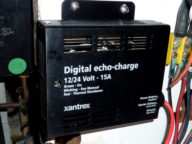
Xantrex Echo Charger (LINK)
The Xantrex Echo Charger is an electronic battery to battery charger (B2B Charger) or 12v to 12v charger. It DOES NOT combine the banks and the banks remain isolated, meaning current can only flow in one direction. It simply takes or "bleeds" it's power from the charge source or the house bank and when it senses over 13.0 volts energizes and begins charging the reserve bank. When it senses below 13.0 volts it turns charging off.
The Echo Charger can supply up to 15 amps of charge current to the reserve battery while borrowing/bleeding it from the house bank. Normally that battery will be at or near full and you'll rarely ever see it pull more than an amp or two anyway. So, 98% of the time your alts full output heads directly to the house bank. The Echo Charger is also a voltage follower and will follow the incoming voltage to the house bank minus a bit of voltage drop across the unit. When the house goes into float mode so does the reserve bank.
The Echo Charger is also a simple three wire hook up but needs to feed the reserve bank, and pull from the house bank. All charge sources should be fed to the house bank, solar, alternator, wind and shore side charger. This part of the Echo Charger installation is mandatory.
This is an Echo Charger:

The Balmar Duo Charger is similar to the Echo but more expensive and can supply up to 30 amps of charge current.
The Sterling Power Battery to Battery Charger is a very elegant true 12V to 12V charger. It can boost voltage from say a GEL bank at 14.1V to n Odyssey TPPL start battery that needs 14.7V. It can also float when the house bank is still in bulk or absorption. It is a true independent charger not just a voltage follower like the Echo or Duo Charger.
By simply adding an ACR, ECHO, Duo or Sterling B2B, you can still go to your boat and select HOUSE and when you leave select OFF. That's it, simple...
Drawbacks To The 1/BOTH/2/OFF As a "USE" Switch:
Voltage Sags:
Some folks complain of voltage drop out for electronics when starting off the house bank. I have rarely experienced this my installations. We can start our engine and not reset any of our electronics, even down to about 35-40% state of charge, but, we use to use three group 31 "pseudo deep cycle" batteries, which is a decent sized bank. If voltage drop outs occur then your deep cycle battery bank may be too small, ready for replacement or you have some wiring issues. To avoid this you can always start the motor, then flip on the instruments.
This is the voltage dip starting a 44HP 4 cylinder diesel off our deep cycle house bank at the end of their fifth season of service:
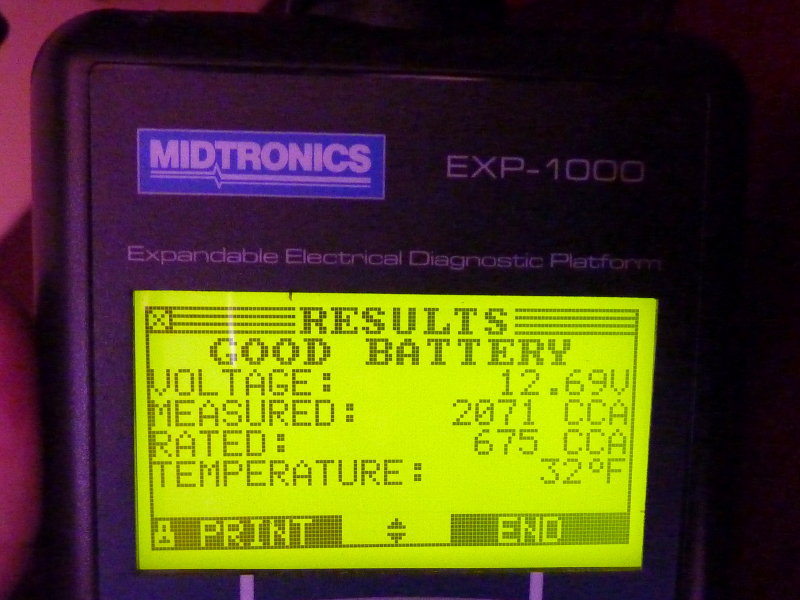
That video was at normal summer temperatures. here is the same bank as measured with a $2000.00 analyzer at 32F battery temp, air temp slightly colder. It should be noted that this was November 2012 at the end of the sixth season of use for these deep cycle batteries.
This photo shows the battery test portion. The bank is still exceeding it's "as new" CCA rating even at 32F. 675CCA X three batteries = 2025CCA she measured 2071 CCA. Resting voltage was 12.69 volts and the rated CCA of each battery is 675 CCA.
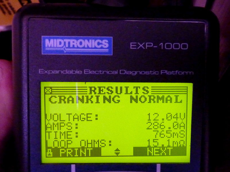
In this second part of the system starting test the analyzer measures average starting current, which will always be higher when it is cold. here the average was 286A. It also measures duration of "cranking", average cranking amps and the circuit resistance. It takes this motor .75 seconds to start... During the starting of this motor, with a 32F battery temp, the average voltage during starting was still 12.04V.. This is significantly higher than what you'd see with a single "starting battery"... Remember this is starting a 4 cylinder 44HP diesel motor at mid 20's Fahrenheit air temp, with a 6 year old house bank of three deep cycle group 31 Wal*Mart batteries..... Even at 32F battery temp there is NO dropout of electronics going on with this installation.
Voltage Spikes/Transients:
In an improperly wired system voltage spikes caused by solenoids, contactors, relays or even DC motors can potentially harm sensitive electronics. On some starter motors for example, that are not internally protected against spikes, when the field around the coil collapses on the starter solenoid it can throw a high voltage spike into the system. Windlass motors, bow thrusters, electric winches, water makers etc. etc.c etc.. can also do the same. The harsh reality is that it is very difficult to get away from the potential for voltage transients on a house bank circuit. Wiring for and creating a "dedicated start bank", that is used only for starting, does not entirely remove the potential for transients. It removes one source but not all potential sources of transients..
Lucky for boaters lead acid batteries make very good filters which can serve to "clamp" these voltage transients. If your DC system loads are wired back to the batteries your likely going to be fine in terms of voltage transients. I measure and test for this on a regular basis with one of the fastest meters out there. It has the capability to capture DC & AC transients at 0.00025 seconds. Yes that is 250 MICROSECONDS. I also have an oscilloscope. What I see regularly is that it is very difficult to pass a damaging voltage spike through a house bank.
Remember our 100+ amp alternators are often supplying upwards of 100A of current to just get the voltage up to 14.6 volts! A properly wired DC panel should not see high level damaging spikes on the DC panel side of the system.
The key is to wire the DC panel neg and positive as close to the bank as is possible and NEVER pick up circuits willy-nilly throughout the vessel. By this I mean NEVER take your depth sounder negative to the engine block or take 12V DC power from the engine panel. Everything must be run back through the DC panel which will have its two large take offs as close to the bank as possible.
If you are concerned about spikes this can be tested in about two minutes with a Fluke 87, 189 or 289 meter. These meters will capture transient voltage spikes at 250 MICROSECONDS or 0.00025 of 1 second. Any good marine electrician can check this for you if they have an o-scope or one of the meters mentioned. I have both an oscilloscope and a Fluke 289. I use the Fluke 289 in the field and it is an invaluable tool.
As one who physically tests for this the; "You must have a dedicated start battery." crowd often gives me a chuckle as they hit their windlass, electric winches or bow thruster which are connected to the house bank. All that wiring to create a dedicated start battery did what exactly? (wink)
Please don't let an electrician talk you into major wiring changes, based on a fear of voltage transients especially if he is simply shooting from the hip. Have him/her SHOW YOU these voltage transients with the proper tools. If they do not own tools that can capture these transients, and are recommending you spend piles of money to avoid them, they should not be considering themselves "marine electricians"... Any good marine electrician should have the tools to do their job properly and avoid "hip-shoot" advice.
All you need to do is connect the meter to your DC panel negative and positive wires and see of you record a spike from the windlass, starter motor, thruster, electric winches, relays, pumps, solenoids, fridge compressors, engine driven refrigeration etc. etc.. If you do see damaging level transients the issue is likely in your boats wiring practices.
While a dedicated start battery is never a bad idea cost and reality need to be weighed for a suitable outcome. In certain cases creating a dedicated start bank will cost less than re-wiring the boat properly. Course I would always argue for proper wiring but it is your boat and your decision. Nothing wrong with a dedicated start bank but it is not the dire necessity many make it out to be..
1/2/BOTH/OFF + ON/OFF:
You can always direct wire a dedicated start battery but it will be more complicated, and invasive, if you want to retain the ability to start off the house bank in an emergency and retain all the safety and isolation features the 1/BOTH/2/OFF can offer. This is why the 1/BOTH/2/OFF is such a good tool despite it often being so badly maligned.
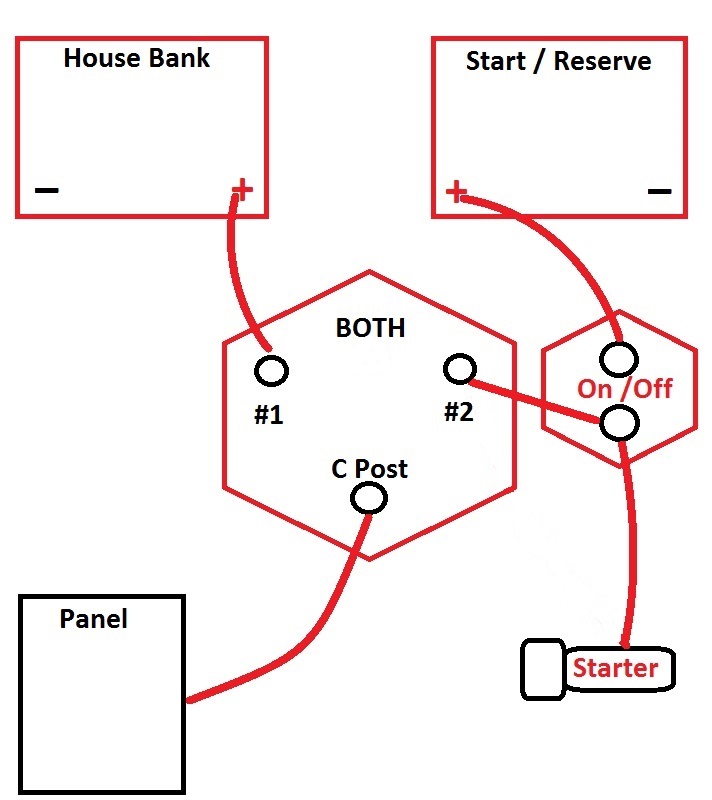
The diagram below is one I like when owners desire a dedicated starting battery but also want to retain the flexibility of the 1/BOTH/2/OFF.
With this simple but very redundant system you retain all the isolation & redundancy of the 1/BOTH/2/OFF switch yet add a dedicated direct wired starting battery. Simply flip to #1 and ON and your ready to go. When you're done flip both switches to OFF. Label them carefully, Blue Sea sells the perfect labels...
If the start battery were to fail flip the ON/OFF to OFF and the 1/BOTH/2/OFF to BOTH and now the house bank is starting and providing house loads. Conversely you can still use the start bank to power house loads in an emergency with the 1/BOTH/2/OFF in position #2 and the start switch to ON.
This system is more complicated but ultimately considerably more flexible than some other systems where you must use the "combine" feature.
For customers with this set up I simply leave a copy of all the scenarios of switch use on-board. This is what it looks like..
NORMAL EVERYDAY USE:
ISOLATED START & HOUSE
Note: Alternator charges HOUSE and Echo Charger charges START.
1/2/ALL = #1
ON/OFF = ON
EMERGENCY SCENARIOS:
START & HOUSE PARALLEL
Note: This overrides the Echo Charger & sends more current to START bank.
1/2/ALL = ALL
ON/OFF = ON
Emergency Situ #1 - START - Provides HOUSE & START Loads:
Note: Use if the HOUSE bank was to fail, for whatever reason. This isolates the HOUSE bank & uses the START bank for everything.
ON/OFF = ON
1/2/ALL = #2
Emergency Situ #2 - HOUSE - Provides HOUSE & START Loads:
Note: Use if the START bank was to fail, for whatever reason. This isolates the START bank & uses the HOUSE bank for everything..
ON/OFF = OFF
1/2/ALL = ALL
Alternative Switch Configurations:
Many have asked what my favorite switch configuration is, if I am not encumbered by a previous installation. When starting from scratch I generally prefer a switch system of three ON/OFF switches. In this situation the alternator and all other charge sources are wired to HOUSE bank and the START gets charged via an ACR or Echo type charger. The EMERGENCY SWITCH could also be used to charge both banks.
It provides:
*Full isolation (fully disconnected) of either bank if necessary
*START bank can be used for both HOUSE and START loads.
*HOUSE bank can be used for both HOUSE and START loads.
*EMERGENCY PARALLEL can be used for charging both banks.
*EMERGENCY PARALLEL can be used to parallel banks.
*STARTING isolation from house loads and electronics.
*HOUSE isolation from START voltage sags or transients.
NOTE: Like the 1/2/B if charge sources are fed direct to the house bank a charge bus and charge bus isolation switch should be used.
Three ON/OFF Switch Configuration:
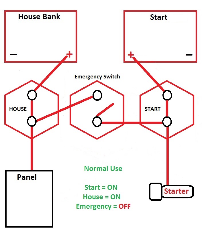
IMPORTANT NOTE: When wiring the three ON/OFF configuration it is very important that the EMERGENCY PARALLEL switch is on the LOAD side of the HOUSE and START switches! I see this configuration IMPROPERLY WIRED very often and incorrect wiring defeats much of the benefits this system provides.
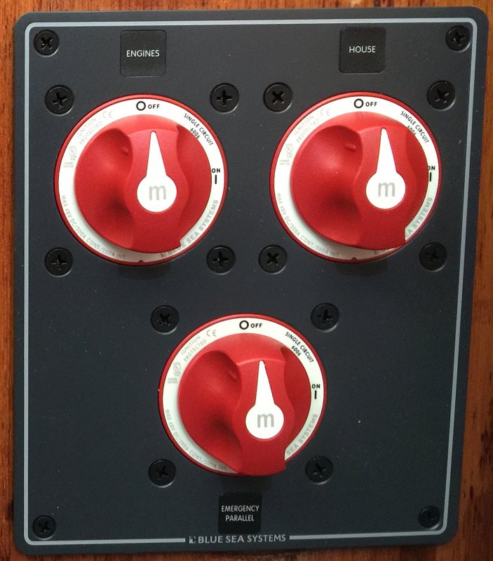
The Blue Sea 8280 makes a great pre-made Three ON/OFF panel that is large enough to hide old holes....
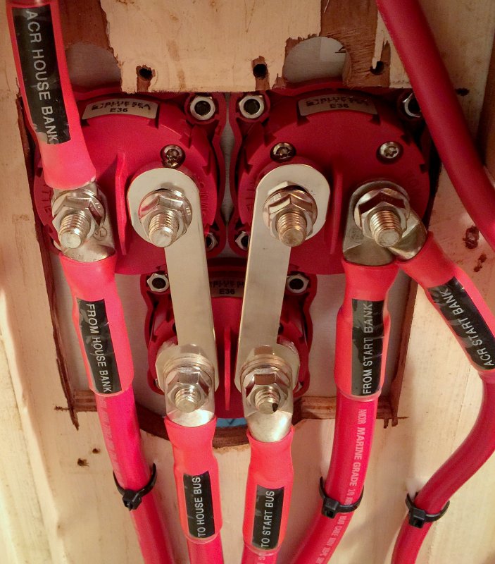
The back side even comes standard with massive tin plated copper busbars. I was able to use this panel to hide some "previous owner" butchery on this particular installation.
What about the Blue Sea Systems "Dual Circuit Plus" Battery Switch?
Pro's of the Dual Circuit Plus:
#1 Simplicity - This is a very simple ON/OFF switch with a "BOTH" feature. Does not get any easier.
#2 Isolates a Starting & House Battery - This can prevent equipment "drop out" on boats with small house banks when the house bank previously got used for starting. As the house banks get larger the drop out of equipment is a non-issue. These were originally designed for fishing boats who start and stop the motor multiple times per day to to prevent the fishing instruments from re-setting. These boats very often have equally sized house and starting banks. The switch can work well in this application whether you have a sailboat or power boat with equally sized small banks..
Drawbacks To The Dual Circuit Plus:
#1 Lacks Proper Isolation - The Dual Circuit Plus switch lacks the ability to properly isolate a failed bank and take it off line while using the "good bank". The only option you have is to "COMBINE" a good bank with a potentially bad one.
#2 No Emergency Reserve Power Position (HOUSE BANK)- The Dual Circuit Plus switch lacks the ability to use the house bank to power both starting and house loads while at the same time isolating the "start" bank from the rest of the system.
#3 No Emergency Reserve Power Position (START BANK)- The Dual Circuit Plus switch lacks the ability to use the starting/reserve battery to power house and starting loads while isolating the "house" bank from the rest of the system.
#4 Incomplete Instructions for a Cruising Boat - The Dual Circuit Plus switch lacks instructions for a wiring configuration with a large house bank (cruising boats) without re-wiring the alternator output. Connecting it via the factory diagram, to a large house bank, will cause relay cycling. As such the alternator output needs to be re-wired to go direct to the house bank when the banks are unequally proportioned
Blue Sea offers a technical brief on this here: Prevent Relay Cycling In Battery Combiners
#5 No Safety Provision for a Failed Bank - With a bank failure, such as an internal short, it forces the user to use the "BOTH/COMBINE" feature and combine a good bank with a failed bank. This can leave a boater dead in the water as it did for one of my customers as recently as last summer. That customer has since switched back to a 1/2/BOTH/OFF with a second ON/OFF for engine start isolation. It is more complicated, as he has two switches to turn ON & OFF, but he has more comfort in knowing he has redundancy and full isolation without the need for using the "BOTH/COMBINE" feature, the same feature that left him dead in the water.. While these failures are rare they can & do happen. Short of re-wiring the system, when a battery dies, you have no way to isolate a bad bank.
#6 Utilize What You Already Have - Most boats already have a perfectly good 1/2/BOTH/OFF switch and the addition of an ACR or Echo Charger will get you the same seamless charging benefit without having to drill more holes in the boat, spend more money or to have less redundancy and isolation. Alternatively a simple ON/OFF can be added to the DCP and give true isolated starting and emergency situations.
So how can I best use a Dual Circuit Plus Switch?
With the addition of two ON/OFF switches, located in the battery compartments, not to be seen by vessel occupants, the DCP switch can be an excellent option because you now have the ability to 100% isolate a bad bank.
Create a charge bus on the load side of the hidden house bank switch and you now have a very good solution...
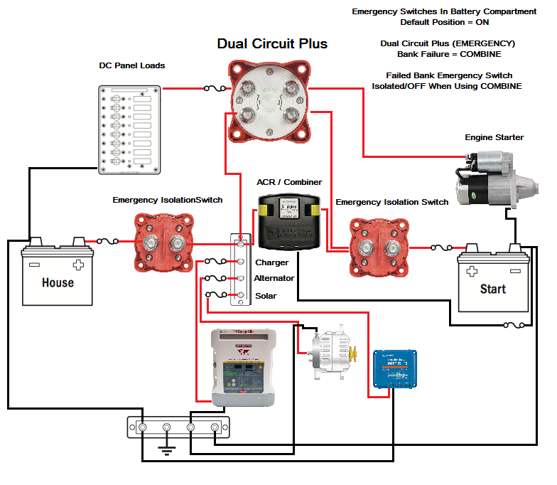
This above diagram is the only way we will install a Dual Circuit Plus switch on a cruising boat but you now have three switches, two of them hidden, as opposed to just one.
Basic Design Principles For Battery Switching:
#1 Bank Isolation - The ability to isolate a battery bank from both loads and charge sources in the event of a bank or battery failure.
#2 Cross Connection Use - The ability to use either on-board battery bank as the sole use bank, meaning it serves as starting and house load bank in an emergency, This design should always include #1.
The 1/BOTH/2/OFF Switch
Over the years most all boat builders, of both sail and power, have installed the simple and redundant 1/BOTH/2/OFF switch. The switch, I believe, has gotten an undeserved bad rap over the years. Why? It's really not necessarily due to the switch itself but rather due to the way most builders install them, and the way many boaters have used them.
Despite the bum rap, the 1/BOTH/2/OFF switch remains a versatile & redundant single-switch battery selector. Surprisingly, even today, they are still the #1 selling multi-bank battery switch made other than the simple ON/OFF. They offer more redundancy and isolation than just about any other easy to use configuration. The "easy to use" part is arguably debatable, hence this post. It should be "easy" but lack of a complete understanding leaves many in a lurch.
Builder Blunders?
The 1/BOTH/2/OFF switch, as wired by builders, becomes a Bank Selection and Charge Directing switch. What, huh? What this means is, what ever position you have the switch set to is where your on-board energy comes from and where the engines alternator charges to.
What Bank Selection and Charge Directing means:
Switch Set to;
Bank 1 = DC loads are drawn from bank #1 and alternator charging goes to bank #1
Bank 2 = DC loads are drawn from bank #2 and alternator charging goes to bank #2
BOTH = DC loads are drawn from BOTH banks and alternator charging goes to BOTH banks
OFF = Both battery banks are isolated/OFF
Note: Even when set to OFF a bilge pump, propane sniffer, stereo memory or VHF may still be direct wired to the house bank so the vessel may still have "live" 12V wires..
Most builders simply wire the alternator circuit back through the starter feed wire to the "C" or common post of the battery switch. This "C" post is the one that gets energized when you flip to 1, 2 or BOTH and is isolated or disconnected when you switch to OFF. This wiring method is CHEAP, easy and gives you lots of options but leaves owners with lots of room for human error and misunderstanding.
This factory wiring works simply and allows you to choose which bank you are charging or drawing from by selecting that bank on the switch. Set it to bank #1 and bank #1 gets charged/discharged. Set it to bank #2 and bank #2 gets charged/discharged. Set it to BOTH and both banks get charged/discharged. Forget to charge bank #1 and bank #1 never gets charged etc. etc.. Leave it on BOTH and run the banks dead and now you're SOL... This is called the Human Error Factor (HEF)..
In this drawing the orange line is showing the switch connecting the house bank to the "loads" via the "C" post of the battery switch. You can visually see the path the alternator takes to get back to the battery bank. The orange line represents the switch position.
Owner Blunders?
So why is this factory wiring bad? It's not necessarily bad if you understand your system and how to use it.
HEF / Human Error Factor Modes;
Blown Alternator Diodes - The big blunders happen when you or a crew mate tries to switch to another bank and you or they pass the battery switch through the OFF position with the engine running and charging the batteries. Passing through OFF, or disconnecting the "load" from the alternator, can cause a massive voltage spike as the "load" or battery bank is disconnected from an alternator while it is trying to charge it and POP goes the diodes.....
Picture, if you will, a bunch of speed skaters in a race. They are moving at full sprint when all off a sudden a Jersey Barrier falls from the sky onto the ice rink. The skaters all pile up and smash into the barrier and boom they are out of commission. This is similar to what happens in your alternator when you shut the battery switch off. All the "flow" piles up with no place to go causing a very fast voltage spike that blows out the diodes.
Damage to Sensitive Electronics - Unfortunately it's not just alternator diodes we need to be concerned with in a battery switch disconnect, though this is what most people notice first, that the alternator is no longer working. If you take a look at where your DC loads are connected this just happens to be the same place as the factory wired alternator. When the switch is opened and the alternator disconnected from the battery, and the alternator is pumping out 70A+, that energy has to go somewhere and it goes straight into your sensitive electronics in the form of a massive voltage transient. This "voltage transient" very often destroys the alternator diodes and also damages DC electronics. It is not uncommon for me to find multiple other items damaged when a customer comes to us for a "bad alternator" and the diagnosis is blown diodes...
In theory the voltage regulator would react and stop this voltage rise, they do limit voltage, but the spike happens too fast for the voltage regulator to react, we're talking damage occurring in microseconds. When you do this there is a high likelihood that the diodes in the alternator will blow and leave you with no alternator and potentially ruined DC electronics too.. This is bad, and the factory wiring does nothing to limit or protect against this. Some newer alternators, on late model engines, utilize "avalanche diodes". Avalanche diodes are more durable but most existing alternators do not have this feature.
The "I Must Set it to BOTH to Start the Motor" Mind Set:
This thinking is flawed and unnecessary, but at the same time it is backed up/supported in some owners minds because it acts as a Band-Aid for weak batteries or a poorly wired system.
A Band-Aid, or better put, BOTH, is only hiding or covering up for "issues" and does nothing to actually solve them. Despite this urban myth, and common boat owner misunderstanding, that you need to use BOTH for starting, you do not need to use BOTH to start your motor. If you do need BOTH to start your motor you have other issues that need to be fixed such as:
- Weak batteries
- Batteries not sufficiently sized to start your motor
- Bad connections in your battery cabling
- Dirty or corroded terminals
The use of BOTH to start you motor, or when charge directing, requires that you remember move the switch off of BOTH when you shut the motor off, or shortly after. Unless you need to be in BOTH for charge directing, there should be no other need for this position in a well operating system that's also properly wired.
Unnecessary switching can lead to blow diodes & massive voltage transients with an inadvertent pass though the OFF position.
The other possible scenario is that an owner has forgotten to switch off of BOTH and killed BOTH BANKS leaving no reserve battery to start the motor with. You'd be surprised how many calls we get each year for this exact issue.
The normal human tendency, when these "blunders" or HEF happens, is to blame the "stupid" 1/BOTH/2/OFF switch. The switch is like a gun, the gun did not pull the trigger the owner of the gun did. How is the gun stupid? It's not, but the owner might be. How is the switch "stupid" when the owner makes a mistake? It's not, it did exactly as it was set to do, but is still often blamed for owner ineptitude or owner HEF. This is the bad rap I referenced earlier.
HEF = Human Error Factor - Humans are perhaps the worst part of the 1/BOTH/2/OFF switch.
So how do you make the 1/BOTH/2/OFF better or more simple to use?
There is little dire need on a small sailboat, with small aux diesel, to need a dedicated starting battery or to use "BOTH" to start your motor. If you need "BOTH", as discussed above, then there is another issue not getting addressed. As always, there are some caveats to this.
Dedicated Starting Battery - A hard wired battery bank used only for starting purposes and nothing else, except for emergencies. It is connected directly to the starter motor when the switch is on.
On our boats, and many of my customers boats, we/they have started our engines, for a long, long time on our house banks as do thousands boaters who use the 1/BOTH/2/OFF switch. We still use the simple, often called "stupid" 1/BOTH/2/OFF switch. The difference is that we only ever use position #1 (HOUSE) and OFF. It is simply a USE SWITCH...
1/BOTH/2/OFF As a USE SWITCH:
We use our switch as a "USE SWITCH" in a SIMPLE ON/OFF scenario. That's it, ON & OFF, or more accurately #1 & OFF. We do not use it as a charge directing switch, or a start on BOTH or #2 then remember to move to #1 switch. It is basically an ON/OFF switch the way we use it. Simple, effective and you likely already have one..
When we use our 1/BOTH/2/OFF switch position #2 (reserve bank) and BOTH are for an emergency only. I don't tend to think in terms of a start and house I think in terms of a reserve and house when using this switch in this configuration. This is but ONE WAY to do this as you'll see further on.
Wiring Upgrades To The 1/BOTH/2/OFF
The 1/BOTH/2/OFF switch is a very useful device and there are a few small changes you can do that can make it even more fool proof. Most of what you need for a very simple and redundant system is already there, so there is little need to spend more money on new switches or drill yet more holes in your boat over what you likely already have. This is of course predicated on the fact that you are comfortable with the idea of not using a "dedicated" starting battery.
To make your 1/BOTH/2/OFF a "USE SWITCH" simply:
1- Make your house bank #1, or "primary"
2- Make the start/reserve battery #2 or "back up/secondary"
3- Install an Automatic Combining Relay (VSR) or an Echo Charger to charge bank #2.
4- (Bonus Option) Feed alternator output directly to the house bank. If doing this it is best to install a battery compartment house bank isolation switch and create a charge "charge bus". If the bank fails you open the isolation switch and all charging now stays with the reserve battery.
Note: #2 as a secondary battery, for me, is always easy to remember but this is just a personal preference. It stems from the days of the Link 2000 & 2000R that necessitated the house bank be on #1 and start/reserve on #2.
Once you've re-wired you now have a USE switch and not a charge directing AND use switch. When you get to the boat simply switch to bank #1, start the motor and go. When you leave the boat simply switch to OFF. You'll use the house batteries for everything including starting. By doing this you'll only ever need to use position #1/House. Behind the scenes, and fully automatically, your emergency (start) bank will always be sufficiently charged via the battery combiner, which takes the place of manually switching to BOTH for charging both banks, or the Echo charger..
If and when the reserve bank is ever needed, and you've also upgraded to an Echo or ACR type charging device, the #2/reserve bank will be ready for an emergency and fully charged. The charging of the start/reserve bank can all be done behind the scenes and is automatic & seamless when you add an ACR/VSR or Echo type charger.
These small changes to convert the 1/BOTH/2/OFF to a USE switch greatly reduces the potential for HEF or memory lapses and makes needless switching, that can lead to blown alternator diodes, a thing of the past.
By wiring the alternator directly to the house bank it will ALWAYS see a load and you'll never need to worry about blowing the diodes by passing the switch through OFF. It is a good idea to install a "service switch" or a switch type circuit breaker, at the battery bank, so you can turn off the alternator feed if and when you're working on the engine. The alternator feed should also be fused as close to the bank as possible.
Echo Charger, Duo Charger or Combining Relay:
If installing an Echo Charger or Duo Charger it becomes necessary to route the alternator output directly to the House bank. This new alternator output wire should be sufficient to carry the entire alternator output with minimal voltage drop and should be fused within 7" of the house bank, or as close as you can. Remember a 3% voltage drop on 14.4V results in just 13.96V at the battery. The often repeated "size for a 3% voltage drop" really should not apply to charging systems, on deeply cycled banks, where the charge source is run for very short periods, if you want optimal charging performance. A 3% voltage drop in a charging system can slow charging and can lead to chronic under charging.
If installing an ACR (voltage sensitive combining relay) it is not entirely necessary to run the alt to the house bank. It is however a very good idea to do so if your house bank is significantly larger than your reserve bank as this can prevent relay cycling if the switch were set to the smaller bank.
Running the alternator output direct to the house bank serves the purpose of entirely preventing the frying of alternator diodes from turning the battery switch through OFF. Even with the engine running you can no longer "pass through OFF"..
What happens if I kill my house bank do I use BOTH then?
If you kill a bank don't fall into the trap of combining the dead bank with a perfectly good one by using the BOTH feature. Simply switch to the second fully charged reserve bank when or if you need to. Combining a good bank with a dead bank only bleeds off precious cranking amps from the good battery, as it tries to bring the voltage of the good battery to parity with the much larger house bank. It will not instantly kill the bank, as many on the net allude to, but there is no need for it, and it can be a bad habit to get into. If the bank has failed, and become an 8V or 10V bank vs. a 12V bank it can actually whack some potential from the bank needed for starting..
The use of BOTH in a dead battery situation is not necessary and can often be more detrimental than good, especially with disproportionately sized battery banks. The most important reason for not using BOTH is that you may not know the reason the house bank is dead . It could be due to an internal short thus creating a 10V battery, instead of a 12V battery.. Can BOTH work? Sure, but there is no need to do so and it can be detrimental. Just isolate the low bank and let the good battery start the motor.
Interestingly enough this past summer a customer lost his regulator and killed both of his battery banks. Dead as in 6.9V! Not paying as much attention as I should have I connected my jumper pack to his 440 Ah house bank of AGM batteries. By the time I got around to the engine switch all I got was "rrrr, rrruh, rrruh" then "click, click". The small jumper pack was not big enough to try and charge the large & very dead house & start banks and have enough left over to start the motor.
I came back the next day and connected the jumper pack directly to the starter battery only and disconnected the house bank. The Yanmar 3GM fired up. The larger your house bank the worse switching to BOTH can be on a small start battery. The jumper pack was able to start the motor via the dead start battery, but not when connected to the 440Ah house AGM bank.
Can my house bank really start my engine?
Yes, it can.. If you are practicing good battery management and never discharging the house bank below 50% state of charge you should always be able to start your engine just fine. This is providing that you have at least a two battery or more house bank and a typical small aux marine diesel or gas engine. If your house bank consists of a single group 24 battery at 50% state of charge you'd be better off to use a dedicated start battery.
Our boat had three group 31 batteries as a house bank. Even though they were "pseudo deep cycle" batteries they still produced a combined CA (cranking amp) capacity of well over 3000 amps at about 65 degrees F. Our single start/reserve battery, in comparison, only has about 1000 CA @ 65F. Our engine manufacturer wants to see about 400 cranking amps.
When you parallel batteries you increase the cranking amps.
It takes VERY LITTLE from your bank to start a small diesel. In fact I can not even measure 0.1 Ah of consumption from a 240 Ah bank, using a Xantrex Link Pro when starting a 44HP four cylinder diesel.
Starting the engine requires very, very little from a battery, many folks over think this and believe it requires a lot more than it really does. Most house banks on cruising sailboats should be much more than necessary to start your engine.
This should show it well:
The 1/BOTH/2/OFF switch can be a great device, if wired & used appropriately & smartly. When wired in the fashion most builders do, and used the way many boaters do, it is less so and thus gets a bad rap.
The 1/BOTH/2/OFF switch retains all the original features & benefits yet looses the frying of diodes and the switching back and forth if you wire the alt direct to the house bank and use an ACR, Echo type charger to top off the start bank.
Redundancy & Isolation Features/Benefits:
* BOTH - Let's just say your ACR or Echo Charger failed, which could happen though is VERY rare, you can still use the ALL/BOTH feature to charge both banks from the alternator just as you always did, even if the alt is routed to the house bank.
* #1 bank can be used to start AND run house loads and can be 100% isolated from second bank.
* # 2 bank can be used to start AND run house loads and can be 100% isolated from second bank.
* You are not forced to combine a good battery with a bad battery bank in an emergency. This can be important especially if a battery bank developed a catastrophic internal fault. With a switch such as the Blue Sea Dual Circuit Plus switch you are required to combine battery banks in an emergency situation. With the 1/BOTH/2/OFF you can simply and completely isolate the bad bank and use the good one.
No Single Right Answer:
As always there is no one right way to wire banks, unless you do it dangerously, but on small boats it often makes little sense to ditch a perfectly good 1/BOTH/2/OFF and drill yet more holes in the boat when a simple re-wire of the existing switch will give you everything you need with simplicity and total redundancy should a combiner fail or a bank suffer a failure..
#1 Assign house bank to batt switch position #1
#2 Install reserve battery to position #2
#3 Wire alternator output directly to the house bank with sufficient size cable & fuse.
#4 Install ACR or Echo Charger between banks.
#5 Use boat in position #1 for starting AND house loads. Switch to OFF when you leave it's that simple.
So why would I want to wire my alt & other charge sources direct to the house bank??
#1 No more worries about fried diodes.
#2 Accurate voltage sensing, less connections & less chance of voltage drop over older factory wiring.
#3 If you use an Echo Charger, Duo Charger or other Battery to Battery type charger you'll need to do this anyway
#4 Allows the house bank voltage to come up to combine voltage before "combining" with the #2 bank. This prevents relay cycling when using an ACR/VSR type device with larger house banks.
When would I Not Wire The Alternator To The House Bank?
Scenario #1: You be best not to wire the alt directly to the house battery unless you have an isolation switch and charge bus. A battery compartment isolation switch on the battery side of the charge bus solves all this and keeps the charge sources with the bank in use..
Why?
If you wire directly to the house bank, bank #1, but do not have an isolation switch at the battery the house bank is still being charged when it has potentially failed. This is not a good practice and would require a wrench to isolate the failed bank from the charge sources. Course a wrench may mean teh alternator is now also removed so a charge bus is always a good idea! An isolation switch & charge bus is a very good idea for a 1/2/B as a use switch.
Follow me here, if you select bank #2 as your source, and the alt & external regulator are connected to bank #1, you will draw down bank two and not replenish it unless the ALL/BOTH function is selected during charging. In short, without an ACR or Echo type charger & a charge bus that can isolate charging from the house bank, I would not suggest wiring directly to the house bank and instead would leave it wired through the common post of the battery switch. As long as you are aware of the dreaded "passing through OFF" then you'll probably be plenty safe. Being educated about "fried diodes" often solves the issue for many of us.
With an ACR/Echo Charger you can still select bank 2 but it will still automatically be getting charged via the combiner or Echo even with the house bank being direct wired to the alternator. Of course this leaves you potentially charging a failed bank..
If you want the utmost in bank isolation, meaning you can take a bank 100% off line and be powered from the other bank, then you want to also be able to isolate the alternator & other charge sources from that bank too. If a battery bank were to fail catastrophically, I've seen it a fair number of times, most recently in August 2011 on a 34 foot Pearson, you would be best served to 100% isolate it by using a charge bus and ON/OFF switch between the house bank and charge bus.. With the alt run direct to the house bank you can't technically totally isolate the bank as it will still be getting charged via the alternator. If the bank had a dead short this may not be the bast place to route it. Best to wire in a charge bus.
These scenarios paint a more positive picture for leaving the alt on the starter post and using an ACR over an Echo Charger for your charge automation. To totally isolate the bank you'd also want an ON/OFF toggle switch on the combining relay unless it too is wired to the charge bus..
So what is a battery combiner / ACR / VSR??
Blue Sea ACR Si Series (LINK)
An ACR is an automatic charging relay. ACR is Blue Sea Systems trade name. They are also know as VSR's or voltage sensitive relays. A VSR is essentially a high current automatic relay that senses voltage and combines banks when the voltage rises. With the Blue Sea ACR if it senses 13.6 volts, for more than 30 seconds, it combines. Also, if it senses more than 13.0 volts for two minutes, it also combines. When the ACR senses a drop in voltage below roughly 12.35V for more than 10 seconds it disconnects or when it senses 12.75V or less for more than 30 seconds it also disconnects the banks. These devices are very simple and fully automatic requiring no human intervention at the battery switch. Truly "set it and forget it" and both banks get charged.
How Does The ACR/VSR Work? Start the engine, and when the charge voltage begins to rise the VSR/ACR automatically energizes the relay, closes it, and "combines" the banks for charging. It is really not much different than if you flipped the battery switch to ALL/BOTH.
The best feature is that they NEVER forgets to disconnect the banks when a charge source is not present. When the batteries are not seeing a charge source they are disconnected & isolated from one another. These devices are relatively inexpensive $65.00 - $150.00 depending upon model. They are also very easy to wire. The Blue Seas ACR has three wires to connect, ground and house and start bank jumpers. Yandina and many others also make battery combiner/VSR products.
The unit labeled ACR is a Blue Seas ACR:
So what is an Echo Charger?
Xantrex Echo Charger (LINK)
The Xantrex Echo Charger is an electronic battery to battery charger (B2B Charger) or 12v to 12v charger. It DOES NOT combine the banks and the banks remain isolated, meaning current can only flow in one direction. It simply takes or "bleeds" it's power from the charge source or the house bank and when it senses over 13.0 volts energizes and begins charging the reserve bank. When it senses below 13.0 volts it turns charging off.
The Echo Charger can supply up to 15 amps of charge current to the reserve battery while borrowing/bleeding it from the house bank. Normally that battery will be at or near full and you'll rarely ever see it pull more than an amp or two anyway. So, 98% of the time your alts full output heads directly to the house bank. The Echo Charger is also a voltage follower and will follow the incoming voltage to the house bank minus a bit of voltage drop across the unit. When the house goes into float mode so does the reserve bank.
The Echo Charger is also a simple three wire hook up but needs to feed the reserve bank, and pull from the house bank. All charge sources should be fed to the house bank, solar, alternator, wind and shore side charger. This part of the Echo Charger installation is mandatory.
This is an Echo Charger:
The Balmar Duo Charger is similar to the Echo but more expensive and can supply up to 30 amps of charge current.
The Sterling Power Battery to Battery Charger is a very elegant true 12V to 12V charger. It can boost voltage from say a GEL bank at 14.1V to n Odyssey TPPL start battery that needs 14.7V. It can also float when the house bank is still in bulk or absorption. It is a true independent charger not just a voltage follower like the Echo or Duo Charger.
By simply adding an ACR, ECHO, Duo or Sterling B2B, you can still go to your boat and select HOUSE and when you leave select OFF. That's it, simple...
Drawbacks To The 1/BOTH/2/OFF As a "USE" Switch:
Voltage Sags:
Some folks complain of voltage drop out for electronics when starting off the house bank. I have rarely experienced this my installations. We can start our engine and not reset any of our electronics, even down to about 35-40% state of charge, but, we use to use three group 31 "pseudo deep cycle" batteries, which is a decent sized bank. If voltage drop outs occur then your deep cycle battery bank may be too small, ready for replacement or you have some wiring issues. To avoid this you can always start the motor, then flip on the instruments.
This is the voltage dip starting a 44HP 4 cylinder diesel off our deep cycle house bank at the end of their fifth season of service:
That video was at normal summer temperatures. here is the same bank as measured with a $2000.00 analyzer at 32F battery temp, air temp slightly colder. It should be noted that this was November 2012 at the end of the sixth season of use for these deep cycle batteries.
This photo shows the battery test portion. The bank is still exceeding it's "as new" CCA rating even at 32F. 675CCA X three batteries = 2025CCA she measured 2071 CCA. Resting voltage was 12.69 volts and the rated CCA of each battery is 675 CCA.
In this second part of the system starting test the analyzer measures average starting current, which will always be higher when it is cold. here the average was 286A. It also measures duration of "cranking", average cranking amps and the circuit resistance. It takes this motor .75 seconds to start... During the starting of this motor, with a 32F battery temp, the average voltage during starting was still 12.04V.. This is significantly higher than what you'd see with a single "starting battery"... Remember this is starting a 4 cylinder 44HP diesel motor at mid 20's Fahrenheit air temp, with a 6 year old house bank of three deep cycle group 31 Wal*Mart batteries..... Even at 32F battery temp there is NO dropout of electronics going on with this installation.
Voltage Spikes/Transients:
In an improperly wired system voltage spikes caused by solenoids, contactors, relays or even DC motors can potentially harm sensitive electronics. On some starter motors for example, that are not internally protected against spikes, when the field around the coil collapses on the starter solenoid it can throw a high voltage spike into the system. Windlass motors, bow thrusters, electric winches, water makers etc. etc.c etc.. can also do the same. The harsh reality is that it is very difficult to get away from the potential for voltage transients on a house bank circuit. Wiring for and creating a "dedicated start bank", that is used only for starting, does not entirely remove the potential for transients. It removes one source but not all potential sources of transients..
Lucky for boaters lead acid batteries make very good filters which can serve to "clamp" these voltage transients. If your DC system loads are wired back to the batteries your likely going to be fine in terms of voltage transients. I measure and test for this on a regular basis with one of the fastest meters out there. It has the capability to capture DC & AC transients at 0.00025 seconds. Yes that is 250 MICROSECONDS. I also have an oscilloscope. What I see regularly is that it is very difficult to pass a damaging voltage spike through a house bank.
Remember our 100+ amp alternators are often supplying upwards of 100A of current to just get the voltage up to 14.6 volts! A properly wired DC panel should not see high level damaging spikes on the DC panel side of the system.
The key is to wire the DC panel neg and positive as close to the bank as is possible and NEVER pick up circuits willy-nilly throughout the vessel. By this I mean NEVER take your depth sounder negative to the engine block or take 12V DC power from the engine panel. Everything must be run back through the DC panel which will have its two large take offs as close to the bank as possible.
If you are concerned about spikes this can be tested in about two minutes with a Fluke 87, 189 or 289 meter. These meters will capture transient voltage spikes at 250 MICROSECONDS or 0.00025 of 1 second. Any good marine electrician can check this for you if they have an o-scope or one of the meters mentioned. I have both an oscilloscope and a Fluke 289. I use the Fluke 289 in the field and it is an invaluable tool.
As one who physically tests for this the; "You must have a dedicated start battery." crowd often gives me a chuckle as they hit their windlass, electric winches or bow thruster which are connected to the house bank. All that wiring to create a dedicated start battery did what exactly? (wink)
Please don't let an electrician talk you into major wiring changes, based on a fear of voltage transients especially if he is simply shooting from the hip. Have him/her SHOW YOU these voltage transients with the proper tools. If they do not own tools that can capture these transients, and are recommending you spend piles of money to avoid them, they should not be considering themselves "marine electricians"... Any good marine electrician should have the tools to do their job properly and avoid "hip-shoot" advice.
All you need to do is connect the meter to your DC panel negative and positive wires and see of you record a spike from the windlass, starter motor, thruster, electric winches, relays, pumps, solenoids, fridge compressors, engine driven refrigeration etc. etc.. If you do see damaging level transients the issue is likely in your boats wiring practices.
While a dedicated start battery is never a bad idea cost and reality need to be weighed for a suitable outcome. In certain cases creating a dedicated start bank will cost less than re-wiring the boat properly. Course I would always argue for proper wiring but it is your boat and your decision. Nothing wrong with a dedicated start bank but it is not the dire necessity many make it out to be..
1/2/BOTH/OFF + ON/OFF:
You can always direct wire a dedicated start battery but it will be more complicated, and invasive, if you want to retain the ability to start off the house bank in an emergency and retain all the safety and isolation features the 1/BOTH/2/OFF can offer. This is why the 1/BOTH/2/OFF is such a good tool despite it often being so badly maligned.
The diagram below is one I like when owners desire a dedicated starting battery but also want to retain the flexibility of the 1/BOTH/2/OFF.
With this simple but very redundant system you retain all the isolation & redundancy of the 1/BOTH/2/OFF switch yet add a dedicated direct wired starting battery. Simply flip to #1 and ON and your ready to go. When you're done flip both switches to OFF. Label them carefully, Blue Sea sells the perfect labels...
If the start battery were to fail flip the ON/OFF to OFF and the 1/BOTH/2/OFF to BOTH and now the house bank is starting and providing house loads. Conversely you can still use the start bank to power house loads in an emergency with the 1/BOTH/2/OFF in position #2 and the start switch to ON.
This system is more complicated but ultimately considerably more flexible than some other systems where you must use the "combine" feature.
For customers with this set up I simply leave a copy of all the scenarios of switch use on-board. This is what it looks like..
NORMAL EVERYDAY USE:
ISOLATED START & HOUSE
Note: Alternator charges HOUSE and Echo Charger charges START.
1/2/ALL = #1
ON/OFF = ON
EMERGENCY SCENARIOS:
START & HOUSE PARALLEL
Note: This overrides the Echo Charger & sends more current to START bank.
1/2/ALL = ALL
ON/OFF = ON
Emergency Situ #1 - START - Provides HOUSE & START Loads:
Note: Use if the HOUSE bank was to fail, for whatever reason. This isolates the HOUSE bank & uses the START bank for everything.
ON/OFF = ON
1/2/ALL = #2
Emergency Situ #2 - HOUSE - Provides HOUSE & START Loads:
Note: Use if the START bank was to fail, for whatever reason. This isolates the START bank & uses the HOUSE bank for everything..
ON/OFF = OFF
1/2/ALL = ALL
Alternative Switch Configurations:
Many have asked what my favorite switch configuration is, if I am not encumbered by a previous installation. When starting from scratch I generally prefer a switch system of three ON/OFF switches. In this situation the alternator and all other charge sources are wired to HOUSE bank and the START gets charged via an ACR or Echo type charger. The EMERGENCY SWITCH could also be used to charge both banks.
It provides:
*Full isolation (fully disconnected) of either bank if necessary
*START bank can be used for both HOUSE and START loads.
*HOUSE bank can be used for both HOUSE and START loads.
*EMERGENCY PARALLEL can be used for charging both banks.
*EMERGENCY PARALLEL can be used to parallel banks.
*STARTING isolation from house loads and electronics.
*HOUSE isolation from START voltage sags or transients.
NOTE: Like the 1/2/B if charge sources are fed direct to the house bank a charge bus and charge bus isolation switch should be used.
Three ON/OFF Switch Configuration:
IMPORTANT NOTE: When wiring the three ON/OFF configuration it is very important that the EMERGENCY PARALLEL switch is on the LOAD side of the HOUSE and START switches! I see this configuration IMPROPERLY WIRED very often and incorrect wiring defeats much of the benefits this system provides.
The Blue Sea 8280 makes a great pre-made Three ON/OFF panel that is large enough to hide old holes....
The back side even comes standard with massive tin plated copper busbars. I was able to use this panel to hide some "previous owner" butchery on this particular installation.
What about the Blue Sea Systems "Dual Circuit Plus" Battery Switch?
Pro's of the Dual Circuit Plus:
#1 Simplicity - This is a very simple ON/OFF switch with a "BOTH" feature. Does not get any easier.
#2 Isolates a Starting & House Battery - This can prevent equipment "drop out" on boats with small house banks when the house bank previously got used for starting. As the house banks get larger the drop out of equipment is a non-issue. These were originally designed for fishing boats who start and stop the motor multiple times per day to to prevent the fishing instruments from re-setting. These boats very often have equally sized house and starting banks. The switch can work well in this application whether you have a sailboat or power boat with equally sized small banks..
Drawbacks To The Dual Circuit Plus:
#1 Lacks Proper Isolation - The Dual Circuit Plus switch lacks the ability to properly isolate a failed bank and take it off line while using the "good bank". The only option you have is to "COMBINE" a good bank with a potentially bad one.
#2 No Emergency Reserve Power Position (HOUSE BANK)- The Dual Circuit Plus switch lacks the ability to use the house bank to power both starting and house loads while at the same time isolating the "start" bank from the rest of the system.
#3 No Emergency Reserve Power Position (START BANK)- The Dual Circuit Plus switch lacks the ability to use the starting/reserve battery to power house and starting loads while isolating the "house" bank from the rest of the system.
#4 Incomplete Instructions for a Cruising Boat - The Dual Circuit Plus switch lacks instructions for a wiring configuration with a large house bank (cruising boats) without re-wiring the alternator output. Connecting it via the factory diagram, to a large house bank, will cause relay cycling. As such the alternator output needs to be re-wired to go direct to the house bank when the banks are unequally proportioned
Blue Sea offers a technical brief on this here: Prevent Relay Cycling In Battery Combiners
#5 No Safety Provision for a Failed Bank - With a bank failure, such as an internal short, it forces the user to use the "BOTH/COMBINE" feature and combine a good bank with a failed bank. This can leave a boater dead in the water as it did for one of my customers as recently as last summer. That customer has since switched back to a 1/2/BOTH/OFF with a second ON/OFF for engine start isolation. It is more complicated, as he has two switches to turn ON & OFF, but he has more comfort in knowing he has redundancy and full isolation without the need for using the "BOTH/COMBINE" feature, the same feature that left him dead in the water.. While these failures are rare they can & do happen. Short of re-wiring the system, when a battery dies, you have no way to isolate a bad bank.
#6 Utilize What You Already Have - Most boats already have a perfectly good 1/2/BOTH/OFF switch and the addition of an ACR or Echo Charger will get you the same seamless charging benefit without having to drill more holes in the boat, spend more money or to have less redundancy and isolation. Alternatively a simple ON/OFF can be added to the DCP and give true isolated starting and emergency situations.
So how can I best use a Dual Circuit Plus Switch?
With the addition of two ON/OFF switches, located in the battery compartments, not to be seen by vessel occupants, the DCP switch can be an excellent option because you now have the ability to 100% isolate a bad bank.
Create a charge bus on the load side of the hidden house bank switch and you now have a very good solution...
This above diagram is the only way we will install a Dual Circuit Plus switch on a cruising boat but you now have three switches, two of them hidden, as opposed to just one.

