It seems that both is the same as combine....."Combine" does exactly that - combine. The purpose of the on-off switches ahead of the DCP is to take a bad bank out of service so that Combine just utilizes the good bank. The reason I like the DCP switch is because it provides service to 2 banks in isolation simultaneously (4 posts - 2 poles). The 1-2-Both switch doesn't have that capability. You can only have one bank or the other on at a time - unless you switch to "Both", which is not preferred.
1/BOTH/2/OFF Switches Thoughts & Musings
- Thread starter Maine Sail
- Start date
The difference is in the two on/off switches in the positive cables (could be wired in anywhere along those cables) from the batteries which is used to isolate a defective battery bank. After that either switch will work to redirect where the remaining power supply is directed - house, starter or both(combine on dcp)
standard 1,2 both only redirects where power is going without isolating a defective bank - this can result in both banks becoming dead- or worse when switched to both.
standard 1,2 both only redirects where power is going without isolating a defective bank - this can result in both banks becoming dead- or worse when switched to both.
The difference is in the two on/off switches in the positive cables from the batteries which is used to isolate a defective battery bank. After that either switch will would work to redirect where the remaining power supply is directed - house, starter or both(combine)
No, that is what the two "hidden" ON/OFF switches are for.Does "combine" take the bad bank out of play or join both banks together?
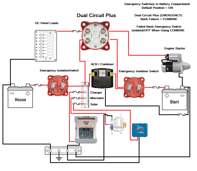
These ON/OFF switches, one for each bank, are typically mounted in the battery compartment close to each bank. In the event of a bank failure that banks ON/OFF is turned to OFF and the DCP switch set to "COMBINE". Now the remaining bank can service the vessel for both start and house loads until you can rectify the issue and the bad bank is fully isolated.
I am rebuilding the electrical system (and everything else) in our Albin Vega 27'. I would like to use a slightly simplified version (smaller banks, no AC charger) of this diagram ...
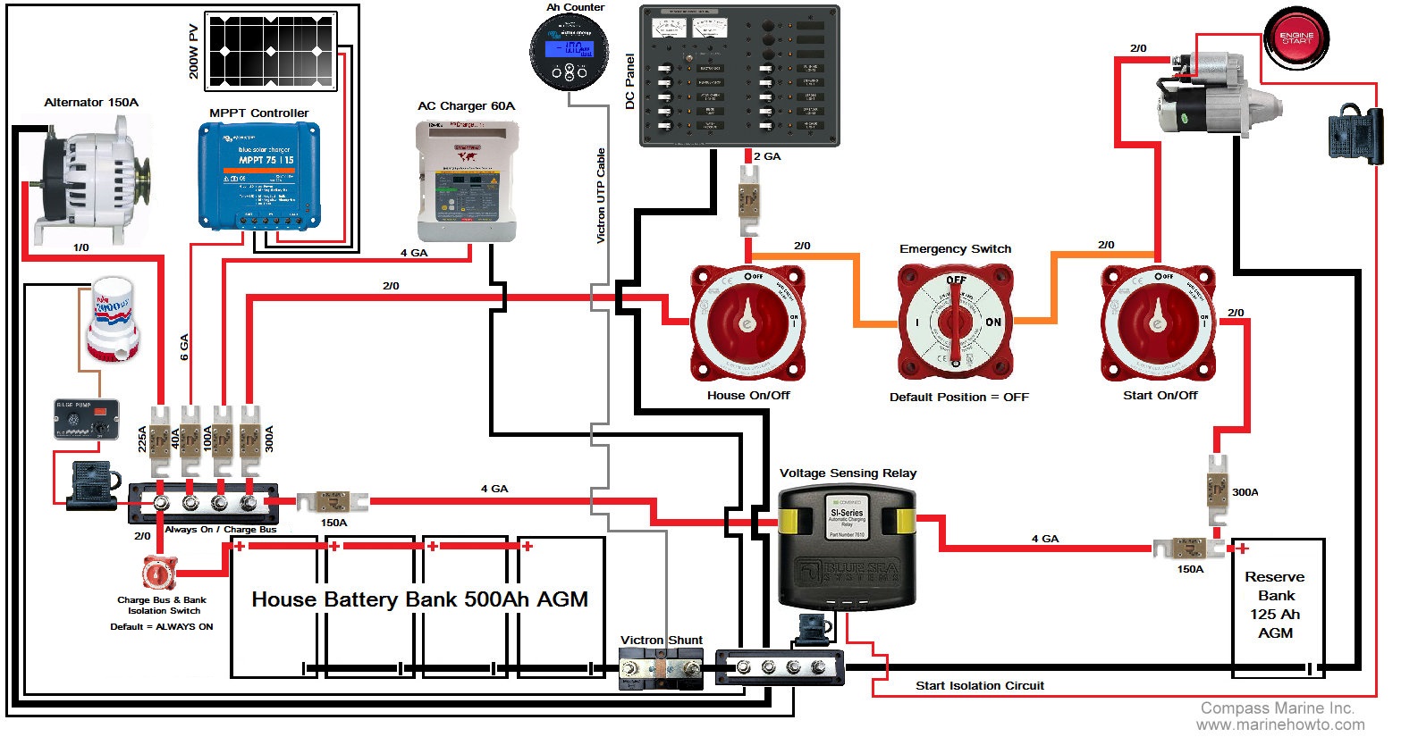
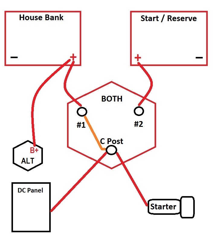
... utilizing a 1/2/BOTH/OFF switch, wired as a "use switch", as shown in this drawing from Maine Sail's original post:
Resulting in the following rough draft of what I hope to build:
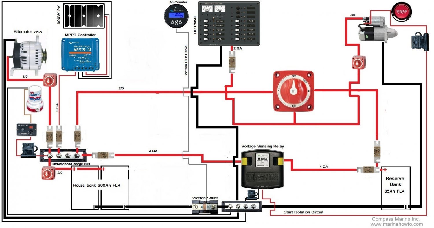
Based on Maine Sail's comments earlier in this thread, I have added an on/off switch to isolate the house bank, and another to isolate the starter. Just a couple questions:
- The reserve/starting battery is isolated by the 1/2/BOTH/OFF switch whenever it is not in use, so no other on/off switch is needed, correct?
- The batteries can never be combined, given the wiring of the 1/2/BOTH/OFF, so is a starter isolation circuit even necessary?
- One other thing (not engine-switch specific, I apologize): in the original diagram, the negative lead from the MPPT controller runs only to the ACR. Neither device is grounded to the foundation. Can this be correct??
Thank you, thank you, thank you to Maine Sail, and everyone else who has helped to build this amazing thread. I've been following it for the past two years. A wealth of knowledge and information is contained here. I would absolutely have to hire an electrician for this job, if not for you guys.
-
... utilizing a 1/2/BOTH/OFF switch, wired as a "use switch", as shown in this drawing from Maine Sail's original post:
Resulting in the following rough draft of what I hope to build:
Based on Maine Sail's comments earlier in this thread, I have added an on/off switch to isolate the house bank, and another to isolate the starter. Just a couple questions:
- The reserve/starting battery is isolated by the 1/2/BOTH/OFF switch whenever it is not in use, so no other on/off switch is needed, correct?
- The batteries can never be combined, given the wiring of the 1/2/BOTH/OFF, so is a starter isolation circuit even necessary?
- One other thing (not engine-switch specific, I apologize): in the original diagram, the negative lead from the MPPT controller runs only to the ACR. Neither device is grounded to the foundation. Can this be correct??
Thank you, thank you, thank you to Maine Sail, and everyone else who has helped to build this amazing thread. I've been following it for the past two years. A wealth of knowledge and information is contained here. I would absolutely have to hire an electrician for this job, if not for you guys.
-
Last edited:
I'm not sure what your purpose would be for the 2 additional isolation switches. The 1+2+B switch already isolates the 2 battery banks assuming that you want the start and house circuits to be on either one bank or the other (except when you set to Both).
The 3-switch diagram shown above doesn't do the same thing as the 1+2+B switch. What's your goal? Do you want start and house circuits to be on separate batteries and do you want to use them at the same time, in isolation? You need 3 on-off switches set up as shown, or - more simply - a DCP switch with 2 isolation on-off switches. With DCP you turn on house and start with just one switch and they are in isolation. The 2 on-off switches are only used to isolate banks when necessary.
Or do you just want house & start to be on the same circuit all the time? For that, just use the 1+2+B without individual switches.
To try to simplify it … The 1+2+B provides for just 1 circuit that you can use on either one bank or the other, or both combined - but start and house will always be on the same circuit, not isolated.
The 3-switch set-up you are referencing provides for 2 circuits in isolation, combined, and/or isolated to just one bank or the other.
The DCP with 2 on-off switches does the same thing as the 3-switch set-up, except more simply.
The 3-switch set-up you are referencing provides for 2 circuits in isolation, combined, and/or isolated to just one bank or the other.
The DCP with 2 on-off switches does the same thing as the 3-switch set-up, except more simply.
Last edited:
Gene, I'm by no means an authority, but I have spent a lot of time figuring out my own system. It appears that you have one "on-off" switch that would only shut down the circuit to the starter. The other "on-off" switch shuts down current between the house bank and the buss bar, which ultimately feeds the 1+2+B switch. I'm just not understanding what that accomplishes.  If you just want to turn off "1", then you just need to switch to "2". And why would you want to abort current to the starter?
If you just want to turn off "1", then you just need to switch to "2". And why would you want to abort current to the starter?You may wish to consider something like the drawing below... The DCP switch (model with combine) can replace the 1/2/B, then in-battery comparment ON/OFF's are used to isolate a bad bank in the event of a bank failure (very rare but they are there for just that purpose). This nice thing about this drawing is that charging stays with the bank being used.I am rebuilding the electrical system (and everything else) in our Albin Vega 27'. I would like to use a slightly simplified version (smaller banks, no AC charger) of this diagram ...
... utilizing a 1/2/BOTH/OFF switch, wired as a "use switch", as shown in this drawing from Maine Sail's original post:
Resulting in the following rough draft of what I hope to build:
Based on Maine Sail's comments earlier in this thread, I have added an on/off switch to isolate the house bank, and another to isolate the starter. Just a couple questions:
- The reserve/starting battery is isolated by the 1/2/BOTH/OFF switch whenever it is not in use, so no other on/off switch is needed, correct?
- The batteries can never be combined, given the wiring of the 1/2/BOTH/OFF, so is a starter isolation circuit even necessary?
- One other thing (not engine-switch specific, I apologize): in the original diagram, the negative lead from the MPPT controller runs only to the ACR. Neither device is grounded to the foundation. Can this be correct??
Thank you, thank you, thank you to Maine Sail, and everyone else who has helped to build this amazing thread. I've been following it for the past two years. A wealth of knowledge and information is contained here. I would absolutely have to hire an electrician for this job, if not for you guys.
-
As I am slowly approching the time when it comes to buy my own boat, and because I care about the boats electric, I have two questions that are not dependent (but connected somehow).
Number 1: It is clear that the boat-AC-ground must not be connected to the boat-AC-neutral as long as boat-AC-ground is connected to shore-AC-ground. However when an isolation transformer is installed (in isolation mode) then boat-AC-ground must be connected to boat-AC-neutral (both the secondary side of the transformer).
Question: shouldn't I install an ELCI on the transformer secondary side just before the ground/neutral connection?
Number 2 (esp. for metal boats): In my understanding for the 12V (or 24V) DC system the same rule should be valid - current back (e.g on the negative side) must be identical to current forward (positive side), or there would be some DC leak which might induce stray current corrosion, even if it is never harmful to persons and wouldn't be even felt. Assuming that the DC lines are generally carried out in a two-wire system (and not using the hull) couldn't be stray current detected by measuring/comparing amperage of positive and negative lines?
Question: is this reasoning somehow correct, and if yes do ELCIs for 12 (24) V DC exist?
Since the battery is the only source/sink of electrons in the DC circuit, the current on the positive and negative lines will always match. The problem is that the electrons may not be taking the right path to get to the positive and negative battery leads. For example, if a bilge pump positive wire gets exposed the current will flow from the + battery terminal to the faulty wiring, then into the water. From the water it will flow back to the prop shaft, to the engine, and through the engine grounding wire back to the battery. From the perspective of the wires connected to the battery everything is balanced, but your prop is the negative electrode in an electrochemical reaction.Number 2 (esp. for metal boats): In my understanding for the 12V (or 24V) DC system the same rule should be valid - current back (e.g on the negative side) must be identical to current forward (positive side), or there would be some DC leak which might induce stray current corrosion, even if it is never harmful to persons and wouldn't be even felt. Assuming that the DC lines are generally carried out in a two-wire system (and not using the hull) couldn't be stray current detected by measuring/comparing amperage of positive and negative lines?
(AC grounding confuses me so I’ll leave question 1 to the pro’s.
This is obviously correct at the battery poles, but I'm talking about a possible amperage difference between the positive and negative wires, not at the battery poles.As I see it there is ground (at least the engine and all bonded items), and the negative line going back to the neg. busbar which is also connected to ground. If you are now measuring the negative return before it reaches the ground bar there would be a difference in amperage between positive and negative in case of stray current using the water or any grounded/bonded items instead of the negative line back, as in your example of the bilge pump.Since the battery is the only source/sink of electrons in the DC circuit, the current on the positive and negative lines will always match.
This is the reason why I am wondering if there are 12/24VDC ELCI on the market? They would simply trip if any stray current occurs.
Please start a new thread. This content does not belong in this thread..
As I am slowly approching the time when it comes to buy my own boat, and because I care about the boats electric, I have two questions that are not dependent (but connected somehow).
Number 1: It is clear that the boat-AC-ground must not be connected to the boat-AC-neutral as long as boat-AC-ground is connected to shore-AC-ground. However when an isolation transformer is installed (in isolation mode) then boat-AC-ground must be connected to boat-AC-neutral (both the secondary side of the transformer).
Question: shouldn't I install an ELCI on the transformer secondary side just before the ground/neutral connection?
Number 2 (esp. for metal boats): In my understanding for the 12V (or 24V) DC system the same rule should be valid - current back (e.g on the negative side) must be identical to current forward (positive side), or there would be some DC leak which might induce stray current corrosion, even if it is never harmful to persons and wouldn't be even felt. Assuming that the DC lines are generally carried out in a two-wire system (and not using the hull) couldn't be stray current detected by measuring/comparing amperage of positive and negative lines?
Question: is this reasoning somehow correct, and if yes do ELCIs for 12 (24) V DC exist?
DonePlease start a new thread. This content does not belong in this thread..
Isolation transformers, and ELCI for DC stray current?A slightly different version with a bit more detail on certain areas can also be found here:Epic post OP! I am in the process of upgrading my battery setup and your original post from 2012 was exactly what I needed. Thoughtful explanations about the motivation behind how to wire a battery system with the trade offs in a digestible length. Excellent.
https://marinehowto.com/1-2-both-battery-switch-considerations/
.
Thanks, I found that one too and read the article on ACRs as well. I do have one question about the use of the ACR in this setup which I haven't been able to find an answer to.
From my understanding the ACR acts as a battery combiner when a charge voltage 13.0+V is sensed (with a variety of response voltages/times based on manufacturer/profile). Assume after being on the hook for a few days that my AGM primary/house bank is at a SOC of 40% and my reserve/start is at 99%. If there is not much power coming from the solar, won't there be a current draw from the start battery to the house battery since the ACR only does a "dumb" connection by shorting the two banks. Or is the fact that there is a higher voltage/pressure on the charge bus prevent that from happening?
This situation is partially addressed here: Making Sense of Automatic Charging Relays - Marine How To
I'm assuming that the test on the 50% SOC battery is using a bench supply that can feed ample current to the battery banks. Does this change if it's a cloudy day and I'm only getting the bare minimum to activate my solar charge controller and feed the banks? An AGM bank can get pretty hungry for current, from my understanding.
I'm not concerned about undercharging the start/reserve since it's never going to be used until the house bank is too dead to start the motor, I'm more concerned about it being drained to charge the primary bank in less than ideal/intermittent charging conditions like I listed above. Is this a legit concern?
I'm ready to pull the trigger on new AGM banks, ACR, charger, solar panels/controller and all the wiring and fuses to make it right. So excited about having a good setup!
You may want to consider installing a 1 or 2 battery switch for each bank that solar will charge. These are switches that DO NOT have a " both or 1&2 " position. The purpose would be to isolate the shore charging from the solar. On a mooring.. select solar... on a dock..shore. Of course the selection is numerical not mooring or dock...Thanks, I found that one too and read the article on ACRs as well. I do have one question about the use of the ACR in this setup which I haven't been able to find an answer to.
From my understanding the ACR acts as a battery combiner when a charge voltage 13.0+V is sensed (with a variety of response voltages/times based on manufacturer/profile). Assume after being on the hook for a few days that my AGM primary/house bank is at a SOC of 40% and my reserve/start is at 99%. If there is not much power coming from the solar, won't there be a current draw from the start battery to the house battery since the ACR only does a "dumb" connection by shorting the two banks. Or is the fact that there is a higher voltage/pressure on the charge bus prevent that from happening?
This situation is partially addressed here: Making Sense of Automatic Charging Relays - Marine How To
I'm assuming that the test on the 50% SOC battery is using a bench supply that can feed ample current to the battery banks. Does this change if it's a cloudy day and I'm only getting the bare minimum to activate my solar charge controller and feed the banks? An AGM bank can get pretty hungry for current, from my understanding.
I'm not concerned about undercharging the start/reserve since it's never going to be used until the house bank is too dead to start the motor, I'm more concerned about it being drained to charge the primary bank in less than ideal/intermittent charging conditions like I listed above. Is this a legit concern?
I'm ready to pull the trigger on new AGM banks, ACR, charger, solar panels/controller and all the wiring and fuses to make it right. So excited about having a good setup!
#1 Your AGM bank should not be at 40% SoC unless they are Firefly Carbon Foam AGM..Thanks, I found that one too and read the article on ACRs as well. I do have one question about the use of the ACR in this setup which I haven't been able to find an answer to.
From my understanding the ACR acts as a battery combiner when a charge voltage 13.0+V is sensed (with a variety of response voltages/times based on manufacturer/profile). Assume after being on the hook for a few days that my AGM primary/house bank is at a SOC of 40% and my reserve/start is at 99%. If there is not much power coming from the solar, won't there be a current draw from the start battery to the house battery since the ACR only does a "dumb" connection by shorting the two banks. Or is the fact that there is a higher voltage/pressure on the charge bus prevent that from happening?
This situation is partially addressed here: Making Sense of Automatic Charging Relays - Marine How To
I'm assuming that the test on the 50% SOC battery is using a bench supply that can feed ample current to the battery banks. Does this change if it's a cloudy day and I'm only getting the bare minimum to activate my solar charge controller and feed the banks? An AGM bank can get pretty hungry for current, from my understanding.
I'm not concerned about undercharging the start/reserve since it's never going to be used until the house bank is too dead to start the motor, I'm more concerned about it being drained to charge the primary bank in less than ideal/intermittent charging conditions like I listed above. Is this a legit concern?
I'm ready to pull the trigger on new AGM banks, ACR, charger, solar panels/controller and all the wiring and fuses to make it right. So excited about having a good setup!
#2 Any voltage above 13.0V is a charging voltage so neither bank can drain into another as they are both seeing a "charging" voltage. If wired correctly, all charging to house bank, you won't even see much if any "in-rush".
#3 If you start at 40% or even 50% SoC, and are charging with low current solar, it will be quite a while before the house bank gets to 13.0V.
All of these points are discussed in the ACR article.
There is no good reason to make it this complicated. Shore charging, solar, alternator, wind, fuel cells and hydro generators all coexist just fine together on the same charge-bus.. Charge the house bank and let a charge management device, such as an ACR, handle the start battery, easy and fully automatic.You may want to consider installing a 1 or 2 battery switch for each bank that solar will charge. These are switches that DO NOT have a " both or 1&2 " position. The purpose would be to isolate the shore charging from the solar. On a mooring.. select solar... on a dock..shore. Of course the selection is numerical not mooring or dock...