I've read many many times that you align the motor to the shaft and not the shaft to the motor which I can appreciate. However, as almost the entire weight of the shaft is on the forward end with the coupler and the shaft pivots on the rubber of the cutlass bearing, the weight does compress this rubber as the forward weight pulls down. To me, this is a problem before the alignment even begins. I pondered this when I re-installed my shaft and noticed I could lift it up a fair amount(which relieved the downward force) as it entered through the packing gland. As it stands now, my shaft is lying relatively close to the bottom of the hull gland and I noticed at idle speed and rotation there appeared to be a bit of a thump. I noticed the engine does "dance" a bit on it's new engine mounts and I am assuming that at that RPM my shaft may me vibrating ever so slightly against my entrance point. We were extremely meticulous at t the alignment. I want to slightly block up the coupler end to compensate for the weight sag/compession of the cutlass bearing and realign. What are your thoughts of the initial lay of the shaft?

Shaft Alignment
- Thread starter Rick2413
- Start date
- Status
- Not open for further replies.

This is a common problem. With my 310 the P.O. had not paid attention to the alignment over the years. As a result of the engine mounts settling the output shaft was contacting at the thru hull at low RPM. I raised the engine to center the shaft and re-aligned. The problem I have now is that the Shaft Log has memory of it's lower position and wants to put downward pressure on the packing gland. So much so that the collar on the nut has started to scored the shaft beacuse the packing is bieing overly compresed. I have put a piece of polypropylene foam under the shaft log to provide some upward force to help neutralize until I can remove the log and re-center it.

Loosen the stuffing box clamps and rotate it 180. Then adjust the rubber hose to be as centered as possible over the shaft with the hose clamps. You'll have enough wiggle room in the rubber to move it side to side up down about 1/8" or more before tightening.This is a common problem. With my 310 the P.O. had not paid attention to the alignment over the years. As a result of the engine mounts settling the output shaft was contacting at the thru hull at low RPM. I raised the engine to center the shaft and re-aligned. The problem I have now is that the Shaft Log has memory of it's lower position and wants to put downward pressure on the packing gland. So much so that the collar on the nut has started to scored the shaft beacuse the packing is bieing overly compresed. I have put a piece of polypropylene foam under the shaft log to provide some upward force to help neutralize until I can remove the log and re-center it.
When not on my phone I will try to help with the first post.

I have never done an engine shaft alignment in a boat, but have done other types. It would seem to me that if you noticed the shaft "hang down" when not connected to the engine then the VERY FIRST part of aligning the Engine to the shaft would have been to Align the shaft thru the Cuttless bearing.
Measure the shaft movement up and down then side to side and be sure it is centered as it comes through the Hull.... THEN align the engine to the centered shaft. Sounds like you aligned the engine to a shaft that was, in reallity, out of alignment with the Cutlas bearing.
I'm sure if i'm off on my way of thinking some one with experience will let us know.
Bee
Measure the shaft movement up and down then side to side and be sure it is centered as it comes through the Hull.... THEN align the engine to the centered shaft. Sounds like you aligned the engine to a shaft that was, in reallity, out of alignment with the Cutlas bearing.
I'm sure if i'm off on my way of thinking some one with experience will let us know.
Bee

I have set up many machines and one boat. The problem with the boat is there is but one shaft support and the stern tube. For my work I made a split wooden bushing that fit the shaft and the stern tube and held the shaft in the center of the stern tube with the hose out of the way. Then I aligned the engine with the shaft, installed the Drivesaver flex coupling abd bolted everything up. Then I removed the spilt wooden bushing and installed my shaft seal.

Rick; it seems to me that if your alignment is really good, that the thump you talk about is not caused by any off center positioning of the packing gland. It would appear to me that the eccentricity that causes the thump would be coming from a worn cutlass bearing or a bent shaft. To get a thumping the shaft has to be turning orbitally, or off the shaft centerline somewhere. With a good alignment it should not be happening at the engine end even if the packing gland is off center. The packing gland is there to keep the water out, and is supposed to float to the shaft. Thats why it's connected to the shaft tube with rubber hose. Even if it were off center so badly that it created an undue force on the shaft to score it it should not have the force to overcome the centering restraint of the coupling.
I would look at the cutlass bearing first. If it has as much play as I think it is probably just worn.
and by way, the others are right, the engine/ transmission CL should have been aligned to the shaft/tube CL first. It would have centered the packing gland much better and your packing would last longer.
Good luck
Joe S
I would look at the cutlass bearing first. If it has as much play as I think it is probably just worn.
and by way, the others are right, the engine/ transmission CL should have been aligned to the shaft/tube CL first. It would have centered the packing gland much better and your packing would last longer.
Good luck
Joe S

You can't have resilient mounts and perfect alignment at the same time without one or two other things, Ross recommends a flexible coupling and I think this is the bare minumum- at least it will compensate for misalignment to some degree. The problem is that when you engage the gear the thrust causes the mounts to deflect, and the engine is immediately out of alignment and will stay that way until the power comes off. On soft mounts like the Yanmar, the engine can move upto 3/4" forward, and will tend to lower itself at the same time. This deflection of the mounts also increases the transmission of vibration (noise) to the hull. The optiumum setup is to take the thrust on a thrust bearing fitted on the shaft behind the coupling. This will keep the shaft in perfect alignment and prevent deflection of the mounts under load. Next is required a cardan shaft or highly flexible coupling (Centa-flex make a good one) to transmit the torque while allowing the engine to move freely on its mounts. Of course it costs more and there isn't always enough space, but if you want a good job you could take Ross's suggestion as your starting point and see if you can add a thrust bearing. My Rasmus was rattly in neutral and also between 1-2000 rpm. This was because the shaft was over three feet in length between the stern gland and gearbox flange, and really needed a support or thrust bearing, and the lack of a bearing along with incredibly soft mounts just lets it all wave aound in the breeze. Kind regards,
Alignment
At first I thought my question sounded totally stupid but as I read the responses it appears that the shaft alignment is not as precise as I've given it credit for. My understanding now is to basically wiggle the shaft left/right, up/down in the strut/cutlass bearing and try to determine the center. Once determined, it is best to support the shaft in this position at the packing gland exit then align the engine to the coupling. If the strut installer was precise, the cutlass bearing is perfect and your guess for center position is good then the shaft should go through the center of the stern tube and alignment should be close. However with the rubber mounts there is no way to prevent the twist from torque unless you install some really fancy alternatives. I originally used an engine template and a string from the cutlass bearing up through the template and adjusted the engine mounts. However, with the weight of the engine, it wasn't even close and redid it all once the shaft and engine were in. Time to wiggle and giggle and try again......Should have asked for help when this first struck me as odd. Thanks all.
At first I thought my question sounded totally stupid but as I read the responses it appears that the shaft alignment is not as precise as I've given it credit for. My understanding now is to basically wiggle the shaft left/right, up/down in the strut/cutlass bearing and try to determine the center. Once determined, it is best to support the shaft in this position at the packing gland exit then align the engine to the coupling. If the strut installer was precise, the cutlass bearing is perfect and your guess for center position is good then the shaft should go through the center of the stern tube and alignment should be close. However with the rubber mounts there is no way to prevent the twist from torque unless you install some really fancy alternatives. I originally used an engine template and a string from the cutlass bearing up through the template and adjusted the engine mounts. However, with the weight of the engine, it wasn't even close and redid it all once the shaft and engine were in. Time to wiggle and giggle and try again......Should have asked for help when this first struck me as odd. Thanks all.
Re: Alignment
The split bushing in the stern tube that I mentioned in my first post takes the guess work out of the shaft location. The engine mounts ought not be so soft as to compress under the weight of the engine. There should be vertical adjustments on the engine mounts for alignment purposes. The feet on my mounts are slotted to allow lateral movement and have jack screw bolts with lock nuts for vertical adjustment. The shaft moves to allow fore and aft adjustment.
The split bushing in the stern tube that I mentioned in my first post takes the guess work out of the shaft location. The engine mounts ought not be so soft as to compress under the weight of the engine. There should be vertical adjustments on the engine mounts for alignment purposes. The feet on my mounts are slotted to allow lateral movement and have jack screw bolts with lock nuts for vertical adjustment. The shaft moves to allow fore and aft adjustment.
R
Ron Chappell
How we did our's...
installation people. Several things change after installation that can affect engine/shaft alignment. First, most initial alignments take place on the hard - in many (especially lighter built hulls) that alignment will often change when the hull is re-stressed upon launch. Also as Dave notes, shaft "sag" is seldom given it's just due in most installation procedures.
Our recent install involved an extra long prop shaft (as is common in double enders)and this "sag" was a real concern. We have set up a number of these in the past and have developed a pretty good feel for whats right, but this particular setup caused me to utilize a temporary support with a bearing installed in it on the forward end of the shaft. With the shaft in this bearing I could move the support incrementally until I felt we had near perfect alignment. In addition, I generally use one size stiffer mounts on Yanmar engines as they tend to be a bit over-rated in my opinion and will (as Dave notes) settle somewhat.
We are fortunate to have an extremely heavy layup for a boat our size, which allowed us the pleasant surprise of absolutely no change in alignment, when the boat was finally returned to the water.
Over the years (again, like Dave)I have come to the conclusion that a Drive Saver flex coupling can be an advantage, as alignment does change slightly over time.
I should clarify - the temporary support/bearing is only used to align the shaft with the shaft-log/cutless bearing. Once this alignment is attained the engine mounts are adjusted to bring the engine into alignment with the shaft.
installation people. Several things change after installation that can affect engine/shaft alignment. First, most initial alignments take place on the hard - in many (especially lighter built hulls) that alignment will often change when the hull is re-stressed upon launch. Also as Dave notes, shaft "sag" is seldom given it's just due in most installation procedures.
Our recent install involved an extra long prop shaft (as is common in double enders)and this "sag" was a real concern. We have set up a number of these in the past and have developed a pretty good feel for whats right, but this particular setup caused me to utilize a temporary support with a bearing installed in it on the forward end of the shaft. With the shaft in this bearing I could move the support incrementally until I felt we had near perfect alignment. In addition, I generally use one size stiffer mounts on Yanmar engines as they tend to be a bit over-rated in my opinion and will (as Dave notes) settle somewhat.
We are fortunate to have an extremely heavy layup for a boat our size, which allowed us the pleasant surprise of absolutely no change in alignment, when the boat was finally returned to the water.
Over the years (again, like Dave)I have come to the conclusion that a Drive Saver flex coupling can be an advantage, as alignment does change slightly over time.
I should clarify - the temporary support/bearing is only used to align the shaft with the shaft-log/cutless bearing. Once this alignment is attained the engine mounts are adjusted to bring the engine into alignment with the shaft.

Thump? After I aligned mine I picked up a "ringing" sound at a certain RPM I attributed to the shaft rubbing on the shaft log. It vanished...but that may have been the result of about 150 miles of near constant operation at cruising speed. If you have a thump...you probably have something else going on, like a loose zinc, bent shaft, fouled prop...etc...in my opinion.
Here's how
The thumping is likely the shaft hitting the shaft log. A cutlass would make that type of noise is if it was severely worn with the shaft spinning dead center in the cutlass but off center it may not. Depending upon zinc location they can wear away unevenly and induce shaft whip other wise it is usually caused by misalignment. The other causes could be a bent shaft, unbalanced prop or a bad motor mount allowing the engine to hop slightly.
Here's the method I use when installing an engine or after having replaced mounts.
1) While on the hard remove or slide the stuffing box forward off the shaft log so you can see the shaft coming through the log.
2) With the coupling attached to the transmission and the bolts only finger tight adjust the engine until you get the shaft centered top to bottom and left to right. Do left to right first, as this is the trickiest, then the up/down. The suggestion Ross made can be used to check centering once you have it visually close. I personally find it much easier to align the shaft to the cutlass & shaft log with it attached to the engine rather than supporting the shaft somehow then aligning the engine to it.
3) While adjusting the up/down & side to side be aware of your gaps between coupling and tranny and use feeler gauges to get it as close as you can during the shaft centering. Heck, it's very easy to center the shaft but then you if you don't pay attention while doing so you could wind up with a 1/8" gap between couplings. Adjusting both at the same time, within reason, you don't need to be exact here, will make finally alignment that much easier. Doing this will ensure that when you do the final alignment you won't knock the centering off much.
Remember this entire procedure is predicated on the premise that the factory built your boat so the shaft log center lines up with the cutlass bearing center. If you are skeptical of this you'll need to confirm these two line up BEFORE doing anything. The shaft log may NOT line up with the cutlass and in this case you want to align the shaft to the cutlass so it rotates perfectly centered in the cutlass and preferably with a new cutlass bearing or only slightly worn. On many boats this means the shaft does not or can not pass through the center of the shaft log without major surgery. This can lead to other issues with stuffing boxes etc.. The engine should be aligned to the cutlass bearing firstly then the shaft log secondly but both are important as you don't want an off center stuffing box wearing the shaft either. On our boat the shaft log and cutlass bearing line up almost perfectly but this is not all that common.
4) With the shaft centered in the cutlass & shaft log begin the fine tuning. I find it best to manually seat the engine after each motor mount adjustment by grabbing the valve cover and wiggling it side to side and back and forth as much as possible. Then re-check with feeler gauges. It will take a while but eventually you will get the coupling to mate to the tranny at .003" or less for a 3- 4" coupling.
5) Re-install the packing box to the stern tube being sure it is in a relaxed position against the shaft and not pressing in one direction or the other. You want it to rest centered over the shaft so the packing nut is not going to rest on the spinning shaft and score it.
6) Once back in the water, with a tuned rig, sail and run the boat for a few hours then re-check the alignment. If it is way off adjust it as close as you can to .004"-.003". With most boats you will find the alignment is off slightly if it is less than .004" perhaps even .005" leave it and continue to use the boat for a few weeks. The boat can take a set and with some this can take a few weeks so it is good to re-check every once in a while. After a few weeks make a final alignment adjustment to .003" or better. As others have said engines move slightly under load, Yamnar more so than others, so starting with a good alignment is a big plus. I have virtually zero vibration on our boat, and also don't have a flexible coupling, but I got my alignment to .002".
When checking alignment do not remove the coupling bolts all the way just loosen them slightly then as you spin the shaft by hand apply a slight hand pressure to the coupling, towards the tranny, if you have a PSS it will do this for you, and check with a .003" feeler gauge in a 360 degree manner. If you're off at say 6:00 to 3:00 on every rotation adjust for that. If your 6:00 to 3:00 alignment moves, say 180 degrees, there is a high likely hood your shaft is bent..
Note: With a new engine or with new mounts you'll want to re-check the cutlass & tube centering after the first few hundred hours as the mounts may settle some. This may or may not show up in a drastic coupling measurement if the mounts settle evenly. Yanmar mounts especially, and the Universal & Westerbeke mounts a little less so, are all prone to this. Repeat the above procedure then you should be good for a long while.
Not Centered Yet: (the white tape is how deep to re-install my PSS bellows)
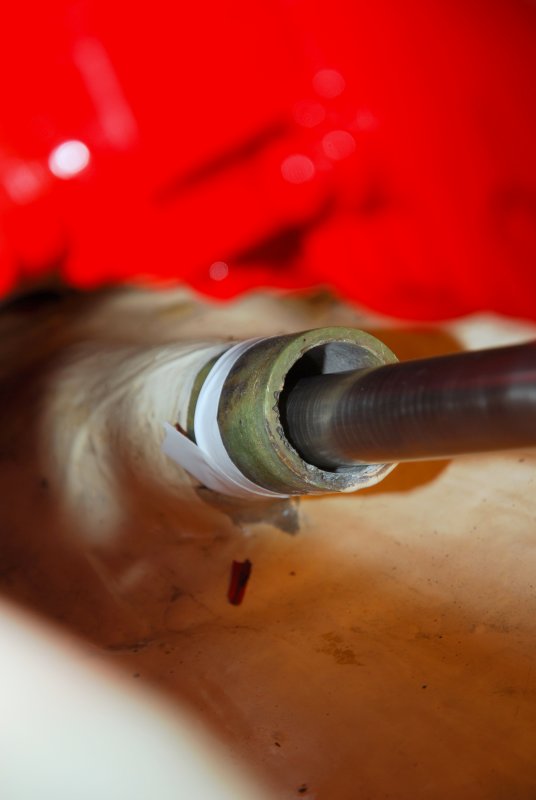
P.S. I'm sure I forgot something and will re-read after my meeting..
The thumping is likely the shaft hitting the shaft log. A cutlass would make that type of noise is if it was severely worn with the shaft spinning dead center in the cutlass but off center it may not. Depending upon zinc location they can wear away unevenly and induce shaft whip other wise it is usually caused by misalignment. The other causes could be a bent shaft, unbalanced prop or a bad motor mount allowing the engine to hop slightly.
Here's the method I use when installing an engine or after having replaced mounts.
1) While on the hard remove or slide the stuffing box forward off the shaft log so you can see the shaft coming through the log.
2) With the coupling attached to the transmission and the bolts only finger tight adjust the engine until you get the shaft centered top to bottom and left to right. Do left to right first, as this is the trickiest, then the up/down. The suggestion Ross made can be used to check centering once you have it visually close. I personally find it much easier to align the shaft to the cutlass & shaft log with it attached to the engine rather than supporting the shaft somehow then aligning the engine to it.
3) While adjusting the up/down & side to side be aware of your gaps between coupling and tranny and use feeler gauges to get it as close as you can during the shaft centering. Heck, it's very easy to center the shaft but then you if you don't pay attention while doing so you could wind up with a 1/8" gap between couplings. Adjusting both at the same time, within reason, you don't need to be exact here, will make finally alignment that much easier. Doing this will ensure that when you do the final alignment you won't knock the centering off much.
Remember this entire procedure is predicated on the premise that the factory built your boat so the shaft log center lines up with the cutlass bearing center. If you are skeptical of this you'll need to confirm these two line up BEFORE doing anything. The shaft log may NOT line up with the cutlass and in this case you want to align the shaft to the cutlass so it rotates perfectly centered in the cutlass and preferably with a new cutlass bearing or only slightly worn. On many boats this means the shaft does not or can not pass through the center of the shaft log without major surgery. This can lead to other issues with stuffing boxes etc.. The engine should be aligned to the cutlass bearing firstly then the shaft log secondly but both are important as you don't want an off center stuffing box wearing the shaft either. On our boat the shaft log and cutlass bearing line up almost perfectly but this is not all that common.
4) With the shaft centered in the cutlass & shaft log begin the fine tuning. I find it best to manually seat the engine after each motor mount adjustment by grabbing the valve cover and wiggling it side to side and back and forth as much as possible. Then re-check with feeler gauges. It will take a while but eventually you will get the coupling to mate to the tranny at .003" or less for a 3- 4" coupling.
5) Re-install the packing box to the stern tube being sure it is in a relaxed position against the shaft and not pressing in one direction or the other. You want it to rest centered over the shaft so the packing nut is not going to rest on the spinning shaft and score it.
6) Once back in the water, with a tuned rig, sail and run the boat for a few hours then re-check the alignment. If it is way off adjust it as close as you can to .004"-.003". With most boats you will find the alignment is off slightly if it is less than .004" perhaps even .005" leave it and continue to use the boat for a few weeks. The boat can take a set and with some this can take a few weeks so it is good to re-check every once in a while. After a few weeks make a final alignment adjustment to .003" or better. As others have said engines move slightly under load, Yamnar more so than others, so starting with a good alignment is a big plus. I have virtually zero vibration on our boat, and also don't have a flexible coupling, but I got my alignment to .002".
When checking alignment do not remove the coupling bolts all the way just loosen them slightly then as you spin the shaft by hand apply a slight hand pressure to the coupling, towards the tranny, if you have a PSS it will do this for you, and check with a .003" feeler gauge in a 360 degree manner. If you're off at say 6:00 to 3:00 on every rotation adjust for that. If your 6:00 to 3:00 alignment moves, say 180 degrees, there is a high likely hood your shaft is bent..
Note: With a new engine or with new mounts you'll want to re-check the cutlass & tube centering after the first few hundred hours as the mounts may settle some. This may or may not show up in a drastic coupling measurement if the mounts settle evenly. Yanmar mounts especially, and the Universal & Westerbeke mounts a little less so, are all prone to this. Repeat the above procedure then you should be good for a long while.
Not Centered Yet: (the white tape is how deep to re-install my PSS bellows)
P.S. I'm sure I forgot something and will re-read after my meeting..

You are correct. To maintain 'concentricity' of the 'assembly' of propshaft, profshaft log/syuffing box, soft/flex coupler, etc., the shaft must FIRST be aligned with the CUTLESS bearing. With a new or relatively un-worn cutless this is easy (not as easy with a worn/deformed cutless).I've read many many ......... I want to slightly block up the coupler end to compensate for the weight sag/compession of the cutlass bearing and realign. What are your thoughts of the initial lay of the shaft?
1. Remove the shaft, and have the journal surfaces where the shaft runs on the cutless and the packing journal area 'dressed'. Dressing will correct any surface irregularities and restore 'concentricity' or 'run-out'. Also check the shaft for any 'bends' .... you want a shaft that is concentric and 'true'. 0.001 to 0.003 is the maximum 'run-out' permitted
2. With the shaft installed in the cutless, slowly 'orbit' the coupler end of the shaft and find the the approximate 'center of orbit' of the shaft, then 'block' the shaft in the approximate position using wood shims, etc. This will ensure that the shaft is running parallel to the longitudinal axis of the cutless and vice versa.
3. Next check the dimensional clearance that the shaft makes with the 'shaft log' & stuffing box, measure to the closest 1/16". Measure from the shaft to the ID of the stuffing box at 0°, 90°. 180° and 270°. If 'off' by more than 1/16-1/8" you should then 'realign' the rubber tube and stuffing box TO the shaft being held in place with the blocks. This will insuure that the stuffing box is imparting equal 'side loads' to the shaft when it is 'packed' with packing. Do not install packing at this time.
4. Align the ENGINE and coupler to the position of the 'held in place' and centered (centered in 'orbit') shaft. Attempt to align the engine to 'perfect' face to face alignment ... coupler faces are exactly parallel to below 0.001" measured around the entire outter margin of the coupler faces. Once the coupler is installed, use a dial indicator (micrometer) and turn the shaft to insure 'true' concentricity of the shaft - (no adverse 'side loading' due to improperly installed packing, etc..
5. Repack the stuffing box.
6. Recheck run-out and concentricity (as above)
This will insure that the shaft is aligned to the cutless, so that the shaft has 'constant clearance' through the cutless, will insure that the flex coupler is running true and is not imparting 'side loads' to the shafting, will insure that the packing is not imparting 'side loads'. Errant side loads on the shaft are the cause of 'shaft whip' ('thumping' at high speeds ... similar to a shaft that is 'behaving like a jump-rope'.
If you are careful and diligent and with the goal of perfection in alignment, you will have a smooth running shaft which will not prematurely wear the cutless, will not 'make noise' at higher rpm.
The flex coupler's function to absorb engine misalignment from 'shaking' and engine harmonics', NOT to correct misalignment of the engine (mounts) nor misalignment of the shaft in the cutless or misalignment due to incorrect packing pressure on the shaft; therefore alignment with respect to the engine/coupler should be near 'perfect'.
Last edited:
S
Suicidalbadger
bearing carrier alignment
Interesting reading, as some people have highlighted the age old problem of rubber bearings.
Use a resilient bearing such as fully composite bearing and the shaft will not sag, or only by a fraction of a mm. You can also use these as a test of carrier alignment. With the shaft chocked a new bearing that is a clearance fit can be rotated easily in the carrier and on the shaft. If you can do this the carrier is aligned. Then just epoxy the bearing in place and leave the shaft chocked until the epoxy sets. You now have a shaft held by a hard bearing that is aligned. Bearings are there to hold a shaft in alignment, the engine moving will extert a force on the shaft that the water film can support, or you can reduce the loads by having a flexible coupling. A soft rubber bearing allows the shaft to move around which is not what you are aiming for.
Interesting reading, as some people have highlighted the age old problem of rubber bearings.
Use a resilient bearing such as fully composite bearing and the shaft will not sag, or only by a fraction of a mm. You can also use these as a test of carrier alignment. With the shaft chocked a new bearing that is a clearance fit can be rotated easily in the carrier and on the shaft. If you can do this the carrier is aligned. Then just epoxy the bearing in place and leave the shaft chocked until the epoxy sets. You now have a shaft held by a hard bearing that is aligned. Bearings are there to hold a shaft in alignment, the engine moving will extert a force on the shaft that the water film can support, or you can reduce the loads by having a flexible coupling. A soft rubber bearing allows the shaft to move around which is not what you are aiming for.
You are correct. To maintain 'concentricity' of the 'assembly' of propshaft, profshaft log/syuffing box, soft/flex coupler, etc., the shaft must FIRST be aligned with CUTLESS bearing. With a new or relatively un-won cutless this is easy (not as easy with a worn/deformed cutless).
1. Remove the shaft, and have the journal surfaces where the shaft runs on the cutless and the packing 'dressed'. Dressing will correct any surface irregularities and restore 'concentricity' or 'run-out'. Also check the shaft for any 'bends' .... you want a shaft that is concentric and 'true'. 0.001 to 0.003 is the maximum 'run-out' permitted
2. With the shaft installed in the cutless, slowly 'orbit' the coupler end of the shaft and find the the approximate 'center of orbit' of the shaft, then 'block' the shaft in the approximate position using wood shims, etc. This will ensure that the shaft is running parallel to the longitudinal axis of the cutless and vice versa.
3. Next check the dimensional clearance that the shaft makes with the 'shaft log' & stuffing box, measure to the closest 1/16". Measure from the shaft to the ID of the stuffing box at 0°, 90°. 180° and 270°. If 'off' by more than 1/6-1/8" you should then 'realign' the rubber tube and stuffing box TO the shaft being held in place with the blocks. This will insuure that the stuffing box is imparting eaual 'side loads' to the shaft when it is 'packed' with packing. Do not install packing at this time.
4. Align the ENGINE and coupler to the position of the 'held in place' and centered (centered in 'orbit' shaft. Attempt to align the engine to 'perfect' face to face alignment ... coupler faces are exactly parallel to below 0.001" measured around the entire outter margin of the coupler faces. Once the coupler is installed, use a dial indicator (micrometer) and turn the shaft to insure 'true' concentricity of the shaft - (no adverse 'side loading' due to improperly installed packing, etc..
5. Repack the stuffing box.
6. Recheck run-out and concentricity (as above)
This will insure that the shaft is aligned to the cutless, so that the shaft has 'constant clearance' through the cutless, will insure that the flex coupler is running true and is not imparting 'side loads' to the shafting, will insure that the packing is not imparting 'side loads'. Errant side loads on the shaft are the cause of 'shaft whip' ('thumping' at high speeds ... similar to a shaft that is 'behaving like a jump-rope'.
If you are careful and diligent and with the goal of perfection in alignment, you will have a smooth running shaft which will not prematurely wear the cutless, will not 'make noise' at higher rpm.
The flex coupler's function to absorb engine misalignment from 'shaking' and engine harmonics', NOT to correct misalignment of the engine (mounts) nor misalignment of the shaft in the cutless or misalignment due to incorrect packing pressure on the shaft; therefore alignment with respect to the engine/coupler should be near 'perfect'.
Re: bearing carrier alignment
This is becoming a short course in a millwright apprenticeship.
I am a bit bewildered about this "Thump". At several hundred rpm the shaft hitting the inside of the stern tube would be a heavy vibration. A thump should be a one time shifting of heavy components. Knocking as with a bad engine bearing is anouther distinct sound. I have had universal joints go bad that made a terrible racket but not a thump. A poorly adjusted pinion shaft will thump when you change direction of rotation.
But centering the shaft in the stern tube is essential. the alignment of the transmission flange and the shaft flange should be square and concentric. The machinery base should be strong enough to maintain this alignment when the boat is moved. If launching changes the alignment then motoring in heavy seas will keep the alignment in constant motion.
This is becoming a short course in a millwright apprenticeship.
I am a bit bewildered about this "Thump". At several hundred rpm the shaft hitting the inside of the stern tube would be a heavy vibration. A thump should be a one time shifting of heavy components. Knocking as with a bad engine bearing is anouther distinct sound. I have had universal joints go bad that made a terrible racket but not a thump. A poorly adjusted pinion shaft will thump when you change direction of rotation.
But centering the shaft in the stern tube is essential. the alignment of the transmission flange and the shaft flange should be square and concentric. The machinery base should be strong enough to maintain this alignment when the boat is moved. If launching changes the alignment then motoring in heavy seas will keep the alignment in constant motion.
Ross --
If the shaft is 'side loaded' by any possible means, then it will when rotating not remain 'true'/straight and will begin to 'precess' (like a jump rope). This is somewhat extremely complex subject into the dark science of 'dynamic balance, as it involves dynamic imbalances in the shaft causing a change of the 'natural frequency' of the 'dynamically bent' shaft to change is "moment of inertia chacteristics" and the 'dynamics' changes the imbalance by many degrees away from the location of the 'center of mass', etc. etc. etc. etc..
The simple statement is the essence of my comments ... do NOT allow any long shaft to receive any side loads - ie.: from packing, from non-aligned bearings, from misaligned engines, from 'BAD' couplers, etc. etc. OR the shaft may start to 'whip' and cause a terrible racket when the new 'changed natural frequency' conditions are met and caused by the 'side loads'. Lets not get into a internet discussion of "induced harmonics" - cant be done 'intuitively'.
If the shaft is 'side loaded' by any possible means, then it will when rotating not remain 'true'/straight and will begin to 'precess' (like a jump rope). This is somewhat extremely complex subject into the dark science of 'dynamic balance, as it involves dynamic imbalances in the shaft causing a change of the 'natural frequency' of the 'dynamically bent' shaft to change is "moment of inertia chacteristics" and the 'dynamics' changes the imbalance by many degrees away from the location of the 'center of mass', etc. etc. etc. etc..
The simple statement is the essence of my comments ... do NOT allow any long shaft to receive any side loads - ie.: from packing, from non-aligned bearings, from misaligned engines, from 'BAD' couplers, etc. etc. OR the shaft may start to 'whip' and cause a terrible racket when the new 'changed natural frequency' conditions are met and caused by the 'side loads'. Lets not get into a internet discussion of "induced harmonics" - cant be done 'intuitively'.
RichH, There must exist a formula for slenderness ratio for shafts just as there is for columns. That is a ratio of diameter and unsupported length. My prop shaft is 3/4 by 34 inches supported by the cutlass bearing and the transmission. I expect that a longer shaft of this diameter could run out when loaded. I have on occassion run very long shafts deliberately flexed and supported by bearings on the ends and sometimes intermediately supported.
Not that easy, as it depends on the natural frequency vs. rpm, 'stiffness'. Its the same reason that you cant statically 'balance' a (most) crankshaft, and have to do it 'dynamically and with standardized 'bob-weights', etc. while its rotating. Too much involved for an 'internet discussion'.
Keep it simple - NO side loads induced by bearings, cutless, couplers, engines, etc. and DO NOT (never ever) depend on the 'flex coupler' to do this job.
Keep it simple - NO side loads induced by bearings, cutless, couplers, engines, etc. and DO NOT (never ever) depend on the 'flex coupler' to do this job.
- Status
- Not open for further replies.