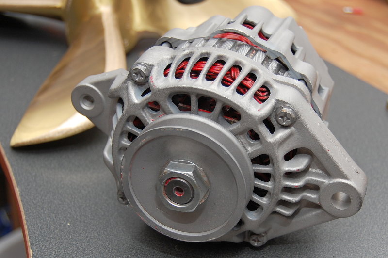
While I had my alternator apart I actually remembered my camera this time. They are not very complicated and the worst part is usually the trouble shooting, if it were to fail. The rebuilding is the fun and easier part. I'd put this as a 5-6 on a 1-10 difficulty scale. This alternator is the stock Mitsubishi unit that came on my Westerbeke 44 B Four engine and is a mere 50 amps..
The first step is to remove the pulley. You definitely will need an impact wrench to do this. If you don't have one bring it by any garage and a mechanic will probably zip it right off for free.
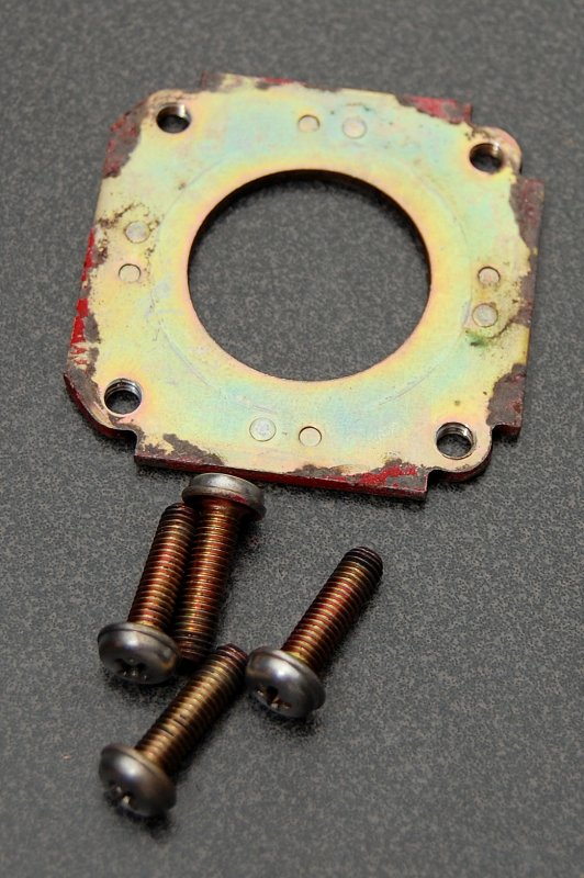
To split or open the case remove the four bolts closest to the edges of the alternator. Once the case is split remove the four machine screws closest to the pulley as these hold the front bearing retainer plate.
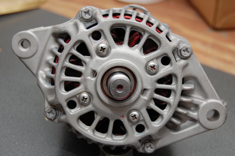
These are the bolts that hold the case together.
The front bearing is the only part in this alternator that I actually replaced. The Westerbeke diesel engine this alternator came off of has 2870 hours on it and this alternator was still in perfect working condition. I only replaced the front bearing because it sees the most wear.
If you are wondering why this alternator is so clean it's because I cheated and had already bead blasted it. I had taken it apart to clean, paint & rebuild but forgot to photograph it the first time. Second time is the charm..")
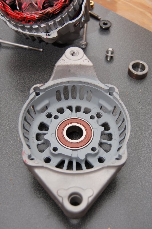
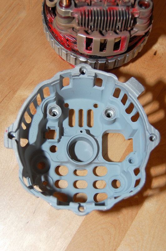
This is the plate that retains the front bearing. To replace the bearing simply remove this plate, press the old one out and order a new one. It takes all of two minutes to replace the front bearing on this particular alternator.
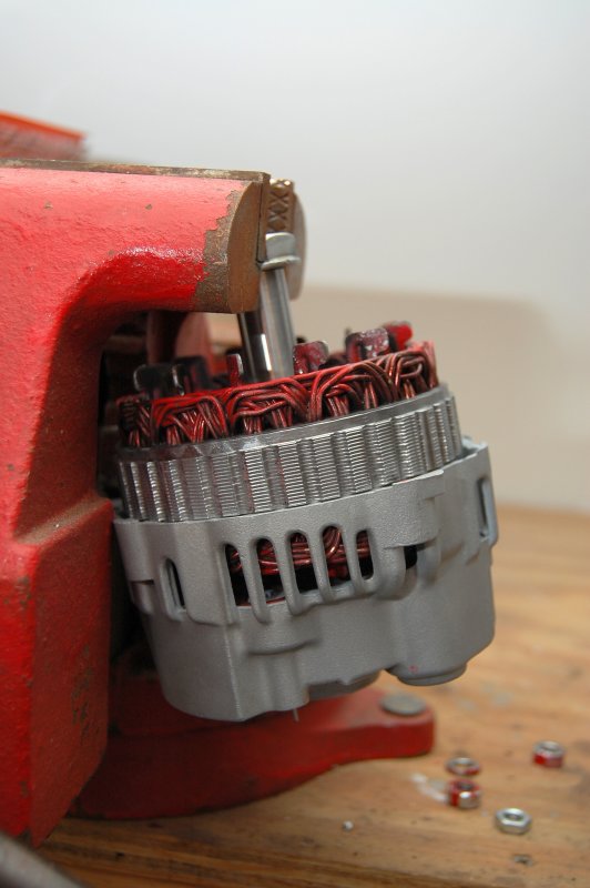
This is where it can become slightly tricky. On this Mitsubishi built alternator the rear bearing is simply a light press fit into the rear case. To remove the rotor I just placed the shaft in the vice, being careful to only grab the shaft nut, and then lightly tapped the case with my lead hammer while rotating it so it came off evenly. I would not use a regular iron hammer to tap on aluminum but it's up to you. Remember this is a light tapping not pounding. Be very careful when tapping the case and removing the rotor as you do not want to damage anything. Many of these small case internal fan alternators are assembled in a similar fashion.
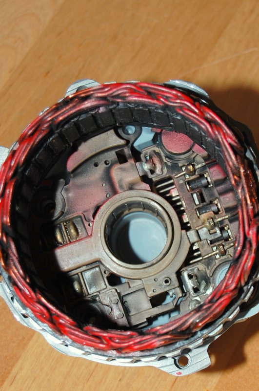
Once the rotor is out all you need to do on this one is remove the three gray screws and pull the stator assembly out. On this unit the brush holder, voltage regulator and stator come out as one unit and the stator is soldered to the regulator/brush holder.
If you are wondering where the brushes are they have been retracted and held back inside the housing for re-assembly, which I'll get to.
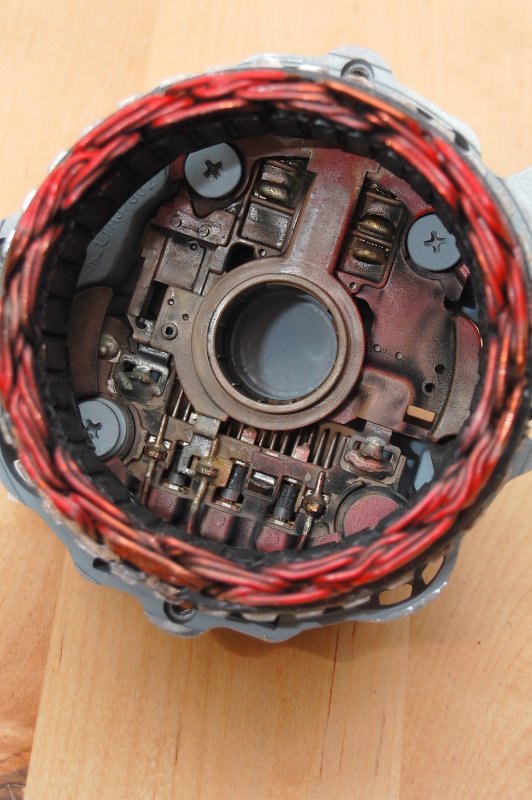
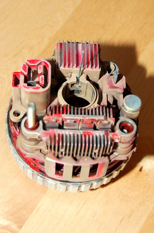
In this photo you'll notice a tiny hole right next to the center bearing location. This is the hole you use to retain the brushes while re-inserting the rotor. You can't re-install the rotor with the brushes in the way so they must be held back.
In this photo you'll notice a 2" long brad nail stuck into a tiny hole next to the brushes. This is how you retain the brushes to re-install the rotor. I found this 2" brad nail to be the perfect tool to retain these brushes.
*****Unfortunately with many of these dual internal fan Japanese style alternators the voltage regulator and brush assembly is all one unit. The voltage regulator and brush assembly is also soldered directly to the stator. While not hard to replace it is more of a pain than the bigger Delco or Hitachi style alternators. Fortunately for me this one is still in perfect condition and operating flawlessly. I'm sure it will run a bit cooler now that I cleaned all the dust and grime out of it too.
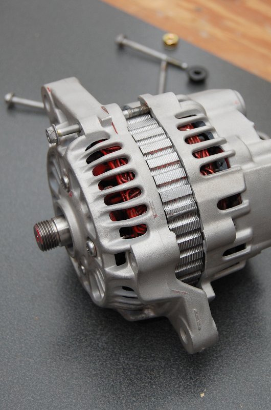
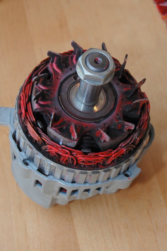
From the left you'll notice the rear bearing & then the copper colored brush contacts which are called slip rings. There are dual fans that are internal to this alternator one on the front and rear sides of the rotor.

Re-Assembly
The first step with an alternator like this one is to retain the brushes, as you saw above. You then line up, and slide, the stator/regulator assembly back into the rear case being very careful to make the brush retaining brad nail slide into the small hole in the rear case.
Sometimes a Sharpie marker is a good way to mark both the stator and the case so you know how they line up & go back together.
Don't forget to re-install the three gray screws before installing the rotor, or what ever holds your stator/regulator assembly is held in place.
In this picture the rotor is set into the case but not yet seated in the rear bearing cavity. To seat this bearing I simply flipped it upside down, with shaft nut on my work bench, and tapped it with my fist then give it one light tap with the lead hammer. Simple!
Remember when I showed you the tiny hole in the rear case? Well this is how it works. You re-assemble the alt then pull out the brad nail or what ever you used to retain the brushes.
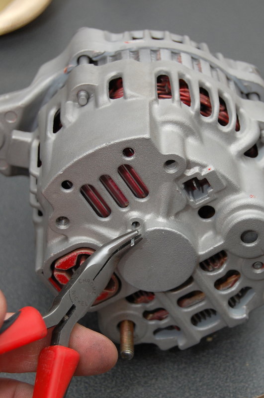
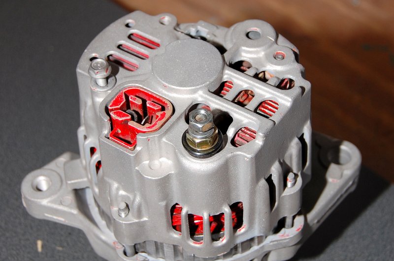
The black plastic ring is to insulate the alternators 12V output stud from the grounded alternator case. Do not forget to reinstall this or you could have a direct short to ground.
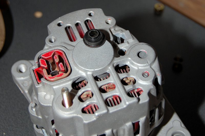
Here you can see that I have reinstalled the ground screw and the retaining bolts for the 12V output stud so the back end is done!
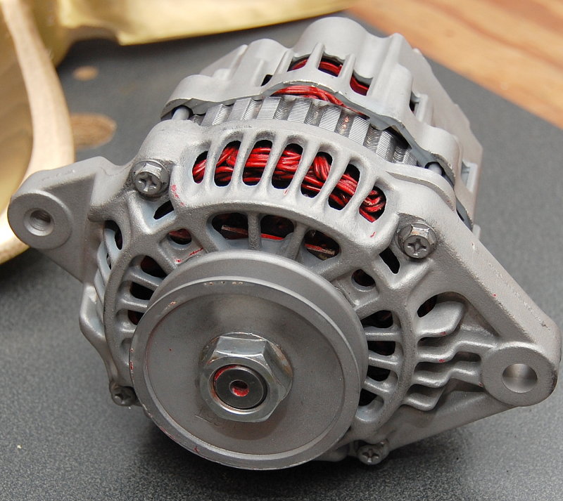
With the front bearing replaced, the internals cleaned, and the case bead blasted and put back together she is ready for a new coat of paint and 2800 more hours..
Repairing or rebuilding an alternator is not a difficult job and most any local alternator shop should be able order you the parts you need. I got my front bearing from the local auto electric shop here in Maine.
These days it's rare to see an alternator wear out and if it does it's often the front bearing or the voltage regulator. Brushes for some reason seem to last eons these days. Perhaps they changed to composition to something better and longer lasting? The brushes in this one are barely worn at 2870 hours of use..
The first step is to remove the pulley. You definitely will need an impact wrench to do this. If you don't have one bring it by any garage and a mechanic will probably zip it right off for free.
To split or open the case remove the four bolts closest to the edges of the alternator. Once the case is split remove the four machine screws closest to the pulley as these hold the front bearing retainer plate.
These are the bolts that hold the case together.
The front bearing is the only part in this alternator that I actually replaced. The Westerbeke diesel engine this alternator came off of has 2870 hours on it and this alternator was still in perfect working condition. I only replaced the front bearing because it sees the most wear.
If you are wondering why this alternator is so clean it's because I cheated and had already bead blasted it. I had taken it apart to clean, paint & rebuild but forgot to photograph it the first time. Second time is the charm..
This is the plate that retains the front bearing. To replace the bearing simply remove this plate, press the old one out and order a new one. It takes all of two minutes to replace the front bearing on this particular alternator.
This is where it can become slightly tricky. On this Mitsubishi built alternator the rear bearing is simply a light press fit into the rear case. To remove the rotor I just placed the shaft in the vice, being careful to only grab the shaft nut, and then lightly tapped the case with my lead hammer while rotating it so it came off evenly. I would not use a regular iron hammer to tap on aluminum but it's up to you. Remember this is a light tapping not pounding. Be very careful when tapping the case and removing the rotor as you do not want to damage anything. Many of these small case internal fan alternators are assembled in a similar fashion.
Once the rotor is out all you need to do on this one is remove the three gray screws and pull the stator assembly out. On this unit the brush holder, voltage regulator and stator come out as one unit and the stator is soldered to the regulator/brush holder.
If you are wondering where the brushes are they have been retracted and held back inside the housing for re-assembly, which I'll get to.
In this photo you'll notice a tiny hole right next to the center bearing location. This is the hole you use to retain the brushes while re-inserting the rotor. You can't re-install the rotor with the brushes in the way so they must be held back.
In this photo you'll notice a 2" long brad nail stuck into a tiny hole next to the brushes. This is how you retain the brushes to re-install the rotor. I found this 2" brad nail to be the perfect tool to retain these brushes.
*****Unfortunately with many of these dual internal fan Japanese style alternators the voltage regulator and brush assembly is all one unit. The voltage regulator and brush assembly is also soldered directly to the stator. While not hard to replace it is more of a pain than the bigger Delco or Hitachi style alternators. Fortunately for me this one is still in perfect condition and operating flawlessly. I'm sure it will run a bit cooler now that I cleaned all the dust and grime out of it too.
From the left you'll notice the rear bearing & then the copper colored brush contacts which are called slip rings. There are dual fans that are internal to this alternator one on the front and rear sides of the rotor.
Re-Assembly
The first step with an alternator like this one is to retain the brushes, as you saw above. You then line up, and slide, the stator/regulator assembly back into the rear case being very careful to make the brush retaining brad nail slide into the small hole in the rear case.
Sometimes a Sharpie marker is a good way to mark both the stator and the case so you know how they line up & go back together.
Don't forget to re-install the three gray screws before installing the rotor, or what ever holds your stator/regulator assembly is held in place.
In this picture the rotor is set into the case but not yet seated in the rear bearing cavity. To seat this bearing I simply flipped it upside down, with shaft nut on my work bench, and tapped it with my fist then give it one light tap with the lead hammer. Simple!
Remember when I showed you the tiny hole in the rear case? Well this is how it works. You re-assemble the alt then pull out the brad nail or what ever you used to retain the brushes.
The black plastic ring is to insulate the alternators 12V output stud from the grounded alternator case. Do not forget to reinstall this or you could have a direct short to ground.
Here you can see that I have reinstalled the ground screw and the retaining bolts for the 12V output stud so the back end is done!
With the front bearing replaced, the internals cleaned, and the case bead blasted and put back together she is ready for a new coat of paint and 2800 more hours..
Repairing or rebuilding an alternator is not a difficult job and most any local alternator shop should be able order you the parts you need. I got my front bearing from the local auto electric shop here in Maine.
These days it's rare to see an alternator wear out and if it does it's often the front bearing or the voltage regulator. Brushes for some reason seem to last eons these days. Perhaps they changed to composition to something better and longer lasting? The brushes in this one are barely worn at 2870 hours of use..

