I will be installing 2 B&G Triton instruments and a Zeus2 - 7 in a nav pod @ the helm. Can I create a backbone in the pod and then use a termination in the pod and a drop to another backbone? I would need to shorten up cables inside the pod to 8" or so. I know that there can't be daisy chained, Trying to avoid running 3 drops though the pedestal.
Navpod with 3 instruments
- Thread starter daviddp
- Start date
We have a similar setup, with a Zeus3 and two Simrad IS40's (equivalent to the Triton). I know we have a Simnet hub in the navpod to interconnect those components with the rest of the backbone. I'm not sure if we have a terminator there but I'll be messing around in there tomorrow so I'll look.
They make “manifolds” with multi device fittings comming out the side and backbone on the ends.
You can’t bridge backbones with device cables but if your navpod is at the end of the line you can put a terminator at one end of the set of T’s or in the end of the manifold. If not at end of line then you need to run two backbone lines up to the navpod. Or if lots of room 3 device drops.
Les
You can’t bridge backbones with device cables but if your navpod is at the end of the line you can put a terminator at one end of the set of T’s or in the end of the manifold. If not at end of line then you need to run two backbone lines up to the navpod. Or if lots of room 3 device drops.
Les
As @LeslieTroyer said use a manifold, like this one: https://www.defender.com/product3.j...-block&path=-1|344|2028705|2028880&id=3655720
Or just string together 3 Tees with a terminator at one end. If you string together the Tees, make sure they are from the same brand. Each brand orients the connectors a little differently, so if you mix a Garmin and a Navico Tee they will not line up, rather they will be at a 45* angle to each other.
Unless you are really cramped for space, use the shortest prefabricated drop cable that you can. It is perfectly permissible to simply coil up the extra cable and secure the coil with small zip ties. Mareton sells premade cables that are 18" long, other companies may sell shorter ones. The Mareton connectors seem to be a little bigger than the Simrad/Lowrance/B&G connectors.
It is possible to make up your own cables using field connectors, but I have found that process to be a skill that I don't care to develop. The few dollars saved by making your own cables will be quickly spent on the proper "medication" to relieve your frustration from working with small wires in tight spaces with even small screws.

Happy New Year!
Or just string together 3 Tees with a terminator at one end. If you string together the Tees, make sure they are from the same brand. Each brand orients the connectors a little differently, so if you mix a Garmin and a Navico Tee they will not line up, rather they will be at a 45* angle to each other.
Unless you are really cramped for space, use the shortest prefabricated drop cable that you can. It is perfectly permissible to simply coil up the extra cable and secure the coil with small zip ties. Mareton sells premade cables that are 18" long, other companies may sell shorter ones. The Mareton connectors seem to be a little bigger than the Simrad/Lowrance/B&G connectors.
It is possible to make up your own cables using field connectors, but I have found that process to be a skill that I don't care to develop. The few dollars saved by making your own cables will be quickly spent on the proper "medication" to relieve your frustration from working with small wires in tight spaces with even small screws.
Happy New Year!
Thanks all for all the great input. I will plan on the Navpod to be the "end of the backbone" That will allow for only one cable through the pedestal guard. I was going to have a manifold anyways so the pod is a good location for that. I'll add power (second location) right before it enters the pedestal in a locker. Now its time to shop for a taller pedestal guard with a bend, mine is not 58" tall.
Last edited:
Consider placing your instruments near the companionway instead of at the helm. Most individual instruments have very large digital displays that can be seen from the helm no matter where they are in the cockpit. The information provided is useful to sail trimmers and other crew members within the cockpit. Be careful not to place them where someone sitting in the cockpit will block them. Your chartplotter should be at the helm. Just my opinion, suit yourself.
Unless you have a lot on your network, you'll only need one power source near the middle (based on the number of devices, not physical distance). Each device on the network has a Load Equivalent Number (LEN) that can be used to determine power needs.Thanks all for all the great input. I will plan on the Navpod to be the "end of the backbone" That will allow for only one cable through the pedestal guard. I was going to have a manifold anyways so the pod is a good location for that. I'll add power (second location) right before it enters the pedestal in a locker. Now its time to shop for a taller pedestal guard with a bend, mine is not 58" tall.
Take a look at this manual, it covers the basics and then some. https://www.maretron.com/products/pdf/Network Installation Guide.pdf
The power goes towards the middle with equal LEN on each side not devices. Probably not an issue if your load is small and network fairly short.
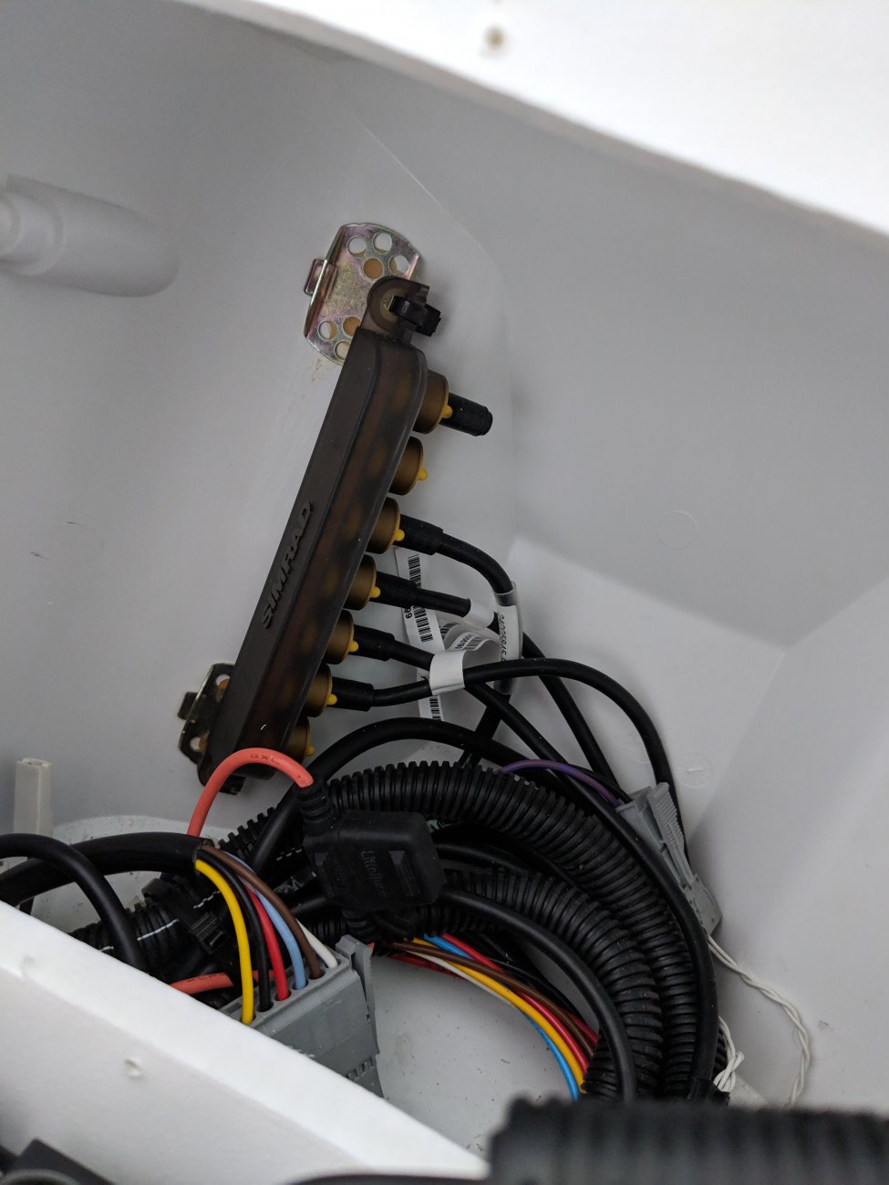
This is how Beneteau wired ours - hub in the navpod with one input from below. The 2 instruments and chartplotter are plugged into the hub. Terminator at the top of this hub. There are 2 additional hubs in the cabin, one of which gets power. The chartplotter is also separately powered, so you will still need to run 2 wires into your pedestal.
I was under the impression that the B & G wind transducer wants to come in at the "end" of the backbone in order to feed info to the instruments properly. I might be mistaken, but that is how I planned mine. If that is the case, you might need to run the transducer cable up into the pod to place it at the end of your manifold. Just a thought, not sure if I'm correct. I actually put mine at the end of the tee instead of the terminator plug, as the transducer is a termination.
The wind transducer is terminated and should go at the end of the backbone. Remember the backbone has 2 ends, at the top of the mast head in the transducer and at the end where the MFD or instruments are.I was under the impression that the B & G wind transducer wants to come in at the "end" of the backbone in order to feed info to the instruments properly. I might be mistaken, but that is how I planned mine. If that is the case, you might need to run the transducer cable up into the pod to place it at the end of your manifold. Just a thought, not sure if I'm correct.
Other thoughts: Read the installation guides about lengths of cables. I don't have it in front of me. I think a drop cable and an extension cable are essentially the same thing physically but serve different purposes. A drop cable is just for the connection of a single instrument. An extension cable would extend your backbone or manifold when you connect it to the ends of the tees, correct? There may be a limitation for the length of extension, but if you are extending to the pod from a place underneath the deck right below, it may not be an issue for you.
Also, my pedestal guard is just 1" diameter, and the plug of the drop cable is more than an inch long. I can't bend it to feed it through a hole in the guard so Ward gave me a splice connector for the location where I had to cut the cable. I'm installing just the chartplotter (not other instruments) at the helm. The connector has 6 ports, while the cable has 5 wires … not a problem I suppose. In the center of the cable, there is an un-insulated strand of silver wire. It's in the center and there is foil shielding inside the cable. Is the exposed wire inside the splice connector going to be an issue? I assume the orientation doesn't matter, as long as the wire colors match. The ports run around in a circle, not oriented like the plug ends of the cable, know what I mean?
Also, my pedestal guard is just 1" diameter, and the plug of the drop cable is more than an inch long. I can't bend it to feed it through a hole in the guard so Ward gave me a splice connector for the location where I had to cut the cable. I'm installing just the chartplotter (not other instruments) at the helm. The connector has 6 ports, while the cable has 5 wires … not a problem I suppose. In the center of the cable, there is an un-insulated strand of silver wire. It's in the center and there is foil shielding inside the cable. Is the exposed wire inside the splice connector going to be an issue? I assume the orientation doesn't matter, as long as the wire colors match. The ports run around in a circle, not oriented like the plug ends of the cable, know what I mean?
Last edited:
That's my impression … I experimented and found that I could either use the termination plug at the end of the manifold and bring the transducer into the backbone as a drop cable at the first Tee in, or, as I settled on, bring the drop cable into the end of the first Tee as the termination. I don't think you can bring a secondary manifold in from the nav pod via a drop cable connection, so if that is true, then he would have to run the wind transducer cable up into the nav pod, which is where the manifold begins, right?The wind transducer is terminated and should go at the end of the backbone. Remember the backbone has 2 ends, at the top of the mast head in the transducer and at the end where the MFD or instruments are.
Just to be clear, the manifold has 2 "ends". I'll call one the upstream end, which is where the wind instrument transducer is connected, and the other end is the downstream end, which needs to be fitted with a termination plug. My kit came with 2 plugs, one male for the upstream end and one female for the downstream end. The power plug wants to be somewhere in the middle.
Last edited:
Another thought about the instrument locations. I have a grouping of instruments on the cabin bulkhead, so that is where I put one of my Tritons. But they are often blocked when Sue is resting her back against them. I thought about putting the second Triton at the helm with the Vulcan chartplotter, but the chartplotter can show your instrument readings, no? So if there is no need for it at the helm, I thought I would put the second one at the base of the mast, as somebody suggested. I haven't pulled the trigger yet on this decision.I will be installing 2 B&G Triton instruments and a Zeus2 - 7 in a nav pod @ the helm. Can I create a backbone in the pod and then use a termination in the pod and a drop to another backbone? I would need to shorten up cables inside the pod to 8" or so. I know that there can't be daisy chained, Trying to avoid running 3 drops though the pedestal.
Which is right?? The navpod and mast top aren’t the only location for N2K drops. I would view the mast as one end of the backbone and navpod at the other, you could swing by the engine, power center, stern (for gps) then to navpod. What ever looks good. I think a going up the mast would be pushing the spec (6 meters for all cable types) for drop cables so for sure it would be one end of the backbone.
You’ve got plenty on interdevice length on the BB and plenty for total length.
Yes the shield has a place to screw down on the field connector.
You’ve got plenty on interdevice length on the BB and plenty for total length.
Yes the shield has a place to screw down on the field connector.
Please follow the spec for placement. What works today but doesn’t follow spec may fail tomorrow as you add equipment or power is lower or or orThat's my impression … I experimented
Your assertion is true but I don’t follow what you mean by transducer cable. The cable leaving the wind transducer is a backbone cable and follow the rules for a backbone. It can go up and connect to a series of T’s or the manifold.I don't think you can bring a secondary manifold in from the nav pod via a drop cable connection, so if that is true, then he would have to run the transducer cable up into the nav pod, which is where the manifold begins, right?
The manifold is just a chunk of backbone cable with drops comming off it. You might want to run the backbone from the mast down to your power panel to pick up power before going aft (that’s ho I would run it for minimal voltage drop)Just to be clear, the manifold has 2 "ends". I'll call one the upstream end, which is where the wind instrument transducer is dropped, and the other end is the downstream end, which needs to be fitted with a termination plug. My kit came with 2 plugs, one male for the upstream end and one female for the downstream end. The power plug wants to be somewhere in the middle.
Correct. An N2K cable is an N2K cable. It becomes a drop or backbone cable depending on how it is used.I think a drop cable and an extension cable are essentially the same thing physically but serve different purposes.
Yes there is a limit on the cable lengths. However on our boats we should never reach that limit as it is fairly large.There may be a limitation for the length of extension, but if you are extending to the pod from a place underneath the deck right below, it may not be an issue for you.
Assuming a knot meter and depth gauge are going to be installed, the backbone would run from the wind transducer to a T near the speed/depth transducer where it would pick up the transducer on a drop cable. The backbone would continue to somewhere near a power source where it would pick up a power tap T and continue on the Nav pod where a manifold or multiple Ts would pick up the instrument displays.I found experimented and found that I could either use the termination plug at the end of the manifold and bring the transducer into the backbone as a drop cable at the first Tee in, or, as I settled on, bring the drop cable into the end of the first Tee as the termination. I don't think you can bring a secondary manifold in from the nav pod via a drop cable connection, so if that is true, then he would have to run the transducer cable up into the nav pod, which is where the manifold begins, right?
If you put the Vulcan at the helm, you'll need at least 2 wires, the N2K cable and a power cable. Drill a bigger hole. See the attached photo. There are 3 cables in the pedestal guard, ethernet, N2K, and power.Also, my pedestal guard is just 1" diameter, and the plug of the extension is more than an inch long. I can't bend it to feed it through a hole in the guard

My Susan does the same thing. You could put one display on each side of the cockpit.But they are often blocked when Sue is resting her back against them.
I understand what you are saying … I have it installed as a backbone cable, like you suggest. I don't recall that the instructions were very clear as to which port to insert it at the 'end' Tee so that is why I experimented (and they provided a male termination plug - I suppose that would only be used if you don't have a wind transducer to plug into the backbone).
I'm not sure what you mean by a "backbone cable with drops coming off". I think of the manifold as that 4-way that you showed, or an assembly of individual Tees. My backbone actually has 8 Tees for 2 instruments, thru hull ducer, auto pilot, Vulcan MFD, backbone power connection, VHF, GPS ant, and the wind ducer comes in at the upstream end of the 8th Tee (so it is a backbone cable). The downstream end has the termination plug.
I'm not sure what you mean by a "backbone cable with drops coming off". I think of the manifold as that 4-way that you showed, or an assembly of individual Tees. My backbone actually has 8 Tees for 2 instruments, thru hull ducer, auto pilot, Vulcan MFD, backbone power connection, VHF, GPS ant, and the wind ducer comes in at the upstream end of the 8th Tee (so it is a backbone cable). The downstream end has the termination plug.
Last edited: