Battery Charging

Feb 6, 1998
11,759
Canadian Sailcraft 36T Casco Bay, ME
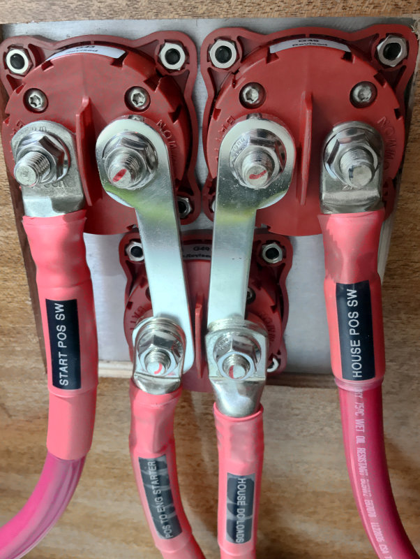
Why builders choose not to use busbars on 150K+ boats is simply frustrating beyond belief. The European builder below had made a similar mess. I gutted the horrendous wiring, replaced the 85A rated battery switches, and cleaned it up. This is what the back of battery switches really should look like. Battery switches were never intended to be busbars..


Catalina really did the owners no favors with that DC design. With just a quick glance..

- If 3/0 wire is required for the thruster then all the battery bank wiring should be 3/0 because you can select BOTH. The largest load on the vessel is what dictates the battery cable size and to keep the load on the banks balanced..

-Non ABYC complaint lug stacking

-Lack of fuses on the house banks = not ABYC compliant
 
May 28, 2015
280
Catalina 385 Atlantic Highlands, NJ
The schematics are helpful.
Note, the schematics aren't exactly what I actually have because the dealer installed several items after delivery such as the inverter. One major difference is that I have the 1-2-All - Engine On/Off combination and not the dual 1-2-All switches. Having now read Maine Sail's post in his special section I'm rethinking that I might actually be better off with the switches I have once the wiring is properly configured

Where are the charging sources, battery charger and alternator connected? Is the alternator a stock internally regulated alternator?

I have to trace each of these next weekend. The alternator and regulator are the ones that shipped. I have questions into the dealer on confirming the actual alternator and the regulator

The 2 house batteries are wired independently of each other and while the batteries are in a parallel circuit in the "both" position, the batteries are not paralleled. Having one large house battery bank is better for the batteries than 2 smaller battery banks. There is more useable power and the batteries last longer.

When properly wired in parallel, batteries last longer because they are maintained at a higher state of charge and are discharged less deeply. Consider this given a 100 amp hour battery with a 10 amp draw for 3 hours. That's 30 amp hours drawn out of the battery or about 30% of the batteries capacity, the SOC is then 70%. However, if you have 2 100 amp hour batteries wired in parallel and take the same 30 amp hours out, the SOC is only 85%, 200 -30 = 170 amp hours remaining. The actual math is a bit more complicated, however, this is accurate enough to illustrate the effect.
I now understand this much better and I agree. My only question is that once in parallel I no longer can measure each house battery independently but I'm not sure that matters. I think I'm better off with the parallel house bank and the starter battery as long as both are being charged when the engine is running (no sense having a reserve battery that is dead because it was never charged). Maine Sail has a solution for that … I just have to figure out how to implement that solution in my environment. See my next post after Maine Sail's observation.
 
May 28, 2015
280
Catalina 385 Atlantic Highlands, NJ
Why builders choose not to use busbars on 150K+ boats is simply frustrating beyond belief.
In fairness, I don't think Catalina rigged the battery switches this way, I'm thinking the dealer rigged the battery switches like this when they added the start battery and inverter (Note the schematics for Catalina's optional starter battery are different than my setup). What has me perplexed is that it appears they are halfway to a clean parallel design but for some reason brought both house bank positive leads to the #1 input on the switch. I would have thought, given the lack of space, that it would have been far easier to run one lead to the #1 input on the switch and rig the house bank in true parallel fashion at the terminals. What I also don't understand is why the bilge alarm would go to the #1 pole of the battery switch … doesn't this allow me to shut it off if I go to Battery #2?

Catalina really did the owners no favors with that DC design. With just a quick glance..
Here I have to take your word for it, I was hoping you were going to say … "The schematics for an Optional Starter Battery are just fine had the installation followed that pathway"

- If 3/0 wire is required for the thruster then all the battery bank wiring should be 3/0 because you can select BOTH. The largest load on the vessel is what dictates the battery cable size and to keep the load on the banks balanced..
This I will need to understand much better. Does this mean I need to bring every wire to/from the engine to 3/0 or do I simply need to make sure my wiring of the house bank parallel setup is 3/0 (or am I completely misunderstanding)?

-Non ABYC complaint lug stacking
-Lack of fuses on the house banks = not ABYC compliant
Here I'm not happy … even I understand this isn't good.
 
Jan 11, 2014
13,994
Sabre 362 113 Fair Haven, NY
My only question is that once in parallel I no longer can measure each house battery independently but I'm not sure that matters. I think I'm better off with the parallel house bank and the starter battery as long as both are being charged when the engine is running (no sense having a reserve battery that is dead because it was never charged).
There's a slight shift in thinking about batteries that makes this all make more sense. Instead of thinking of having 2 house batteries, you have 1 house battery consisting of 12 individual cells housed into 2 separate boxes.

If the batteries start out equal in age, size, and chemistry they will function quite nicely as one unit.
 
May 28, 2015
280
Catalina 385 Atlantic Highlands, NJ
There's a slight shift in thinking about batteries that makes this all make more sense. Instead of thinking of having 2 house batteries, you have 1 house battery consisting of 12 individual cells housed into 2 separate boxes.

If the batteries start out equal in age, size, and chemistry they will function quite nicely as one unit.
Agreed … that journey started in earnest last night whilst reading Maine Sail's posts.

Initially I thought I was hurting my house bank in the current architecture by having it double as the starting battery (ie. using battery switch position #1) but his logic resolved that concern. What I did realize was that while motoring in switch position #1 I am not likely charging my reserve battery. Hence the importance of tracing whether the battery charger is wired to charge the reserve battery (it can handle up to three batteries). My panel's voltmeters are also not wired to my reserve battery so while I've got two dials, it appears to be reading from the two house banks and they are identical (genius … right?).

So … I have to minimally:

1. trace the Alternator wires,
2. trace the Charger wires,
3. likely remove one of the House Bank wires from Input #1,
4. likely reroute the wires that should not have been run to my battery switch (the small wires)
5. properly wire the house bank in parallel at the terminals, and
6. properly connect the voltmeter to the Parallel'd House Bank and the Reserve Battery.

In the process, I'm likely to have the Reserve Battery on (1) and the House Bank on (2) to follow the traditional scheme. If I don't already have an ACR, I might need and ACR in the Alternator line to allow simultaneous charging while motoring.

Maine Sail did present an architecture with the 1-2-All and Engine On/Off switch that allows starting from the Starting Battery and charging both while isolating the house bank to avoid voltage drop … I have to reread that post in detail as that might be the architecture I end up with.

As usual, this site is fantastic and the help you have all provided is very much appreciated.
 
May 28, 2015
280
Catalina 385 Atlantic Highlands, NJ
Well … Update #2 … and this is a good one I think …

This post started 9 days ago with a question: "How can I check the actual amperage output from my alternator and the true amperage input at my battery bank when the alternator is charging?" … the hunch I had at the time was that my alternator wasn't keeping up with my systems … my hunch was wrong … my alternator appears to be doing just fine.

I thought my two house banks were 205Ah each and I thought at the time I was starting my engine from a starter battery (silly me).

Here is what I learned today:
(1) My house bank is made up of two 160 Ah 4D batteries (160 Ah @ 20hr)
(2) My "starter battery was wired by the dealer to battery #2 but not connected to the house charger
(3) I had been running my systems religiously off of battery #1 because that was what I was told to do
(4) My readings posted on Sunday regarding my full load battery test appear to be far more in line with expectations once the 160ah@20hr and Peukert's Law are accounted for.

So while all systems appear to be working properly, I think I just avoided a disaster. Had I left for my overnight trip (125nm 3 miles offshore from NJ to Block Island) and we had favorable winds to sail most of the way … sometime in the middle of the night our systems might have shut down and I might not have had a charged Starter/Reserve battery.

I had an epiphany this morning that I could determine whether the Alternator and/or the Charger were reaching each of the batteries by testing their voltages with a multimeter at each switch position (except Off when the Engine is running) while fully charged, under load, under load with the Engine idling, under load with the Engine at 2000 RPM, and under load with the Charger running.

I've uploaded the results of the tests and the answers were pretty clear. The house is on Switch #1, the Starter/Reserve is on Switch #2. You will note that when the Engine is running and the Switch is in the #1 position, the Starter/Reserve is not receiving any charge. When the Engine is running and the Switch is in the #2 position, the House is not receiving any charge. When the Charger is on and the switch is in the #1 or #2 position, the Starter/Reserve is not receiving any charge. Only when I'm in the "1+2" position is the Starter/Reserve receiving a charge from the charger.

Post Script, even under 23 Amp load the Starter/Reserve battery still started the engine when we tested her today. I left the switch in the "1+2" position with the charger running for a few days to get full charges into each of the batteries (although I'm pretty sure to do this right I need the Starter/Reserve getting a charge on its own independent lead).

My charger can handle 3 batteries but once my House batteries are properly setup in parallel there will no longer be a need for both batteries to receive charge from the charger (I don't think).

Hence my question … with the House in parallel, ought each battery be connected directly to the charger and the third slot used for the Starter/Reserve or should I connect one lead from the charger to the House and one lead from the charger to the Starter/Reserve?

I would love to know from @Maine Sail whether my readings are worthy of interpretation. I feel like a sophomore in the truest sense of the derivation of the word … I have a much better handle on how this system was put together and works (or doesn't as the case may be). Thanks again to everyone ...
 

Attachments

Jan 11, 2014
13,994
Sabre 362 113 Fair Haven, NY
Hence my question … with the House in parallel, ought each battery be connected directly to the charger and the third slot used for the Starter/Reserve or should I connect one lead from the charger to the House and one lead from the charger to the Starter/Reserve?
When you properly parallel the batteries, they act as one big bank, assuming the charger has enough capacity one lead will work.

If the Start and House bank are connected with an ACR it is only necessary to have one lead from the charger to the house bank and then let the start battery charge through the ACR.
 
May 28, 2015
280
Catalina 385 Atlantic Highlands, NJ
Final Update:
The battery charger has now been rewired to charge the Starter/Reserve battery and the House bank using two leads.

I was able to successfully equalize both battery banks and in the process, having disconnected the wires from the battery switch during equalization I was able to trace the five wires on Input post #1. Two of the wires were confirmed to be connected to the house bank batteries. One of the wires was the bilge pump. Finally, the remaining two wires were the voltmeter.

I was advised by the dealer's electrician that if I were to replace the two house wires I would have to use heavier gauge wire and it would have a very hard time making the 90 degree turn at the battery switch. His recommendation was to leave the batteries connected via the two house wires. I have followed this recommendation for now.

One of the two voltmeter wires has been moved back to input post #2 and now I have a voltmeter reading for the Starter/Reserve battery and the House Bank separately (which was what I originally wanted).

My House Bank performance appears to be stronger post-equalization although I am still due to perform a full battery capacity test.

Thanks to all who participated on this project ...
 
Feb 6, 1998
11,759
Canadian Sailcraft 36T Casco Bay, ME
If I don't already have an ACR, I might need and ACR in the Alternator line to allow simultaneous charging while motoring.
Possibly not what you meant but an ACR is NEVER EVER installed in the alternator B+ feed. It gets installed between batteries. Feed all charging sources to house and let the ACR charge start. Best to land all this stuff on a busbar in very close proximity to the house + terminal..
 
May 28, 2015
280
Catalina 385 Atlantic Highlands, NJ
Possibly not what you meant but an ACR is NEVER EVER installed in the alternator B+ feed. It gets installed between batteries. Feed all charging sources to house and let the ACR charge start. Best to land all this stuff on a busbar in very close proximity to the house + terminal..
Oh my gosh … how much I've learned in the last week … dummy me probably did mean what I wrote at that time but looking back with what I know now of course an ACR isn't ever installed in the alternator feed.
 
Apr 8, 2010
2,237
Ericson Yachts Olson 34 28400 Portland OR
Based to a considerable extent on Maine's advice I added a BalMar Smartgauge to our boat. I really like the simplicity of the hookup and the detailed information it provides. You might want to have a look at this also.
 
May 28, 2015
280
Catalina 385 Atlantic Highlands, NJ
Based to a considerable extent on Maine's advice I added a BalMar Smartgauge to our boat. I really like the simplicity of the hookup and the detailed information it provides. You might want to have a look at this also.
Just looked at it … very interesting … and I had a chuckle that two weeks ago none of the features would have made any sense to me but now it makes a lot of sense and I think I would know exactly how and where to install it.

One question … during discharge is it smart enough to compensate for current draw as "under load voltage" will be lower the stronger the current draw. That is the major issue I have for monitoring while underway … I can't remove the load to assess the true state of charge. My plan for the trip is to start the engine if I get uncomfortably low on voltage under load.
 
Jan 11, 2014
13,994
Sabre 362 113 Fair Haven, NY
One question … during discharge is it smart enough to compensate for current draw as "under load voltage" will be lower the stronger the current draw. That is the major issue I have for monitoring while underway … I can't remove the load to assess the true state of charge. My plan for the trip is to start the engine if I get uncomfortably low on voltage under load.
The short answer is yes. The actual algorithm that the SG uses is proprietary, however, we do know it measures voltage and time and likely has some builtin standard tables of SOC and voltage values. The SG requires a few charge/discharge cycles to improve accuracy.

What the SG doesn't do is count amps going in and out, nor does it display current draw. I added a Victron Battery Monitor so I can monitor charging/discharging currents in real time. It doesn't cost that much more than a standard digital ammeter, however, it provides much more information and can be used as a back up to the SG.