
O'Day 222 rudder won't stay down
- Thread starter bobporta
- Start date

The rudder on 192/222 has a downhaul line. There is a coin sized cavity on the leading edge, and a 3/16" line runs up through the headstock to be cleated off on the tiller. It may have run up through the headstock spacers and up over the aft end of the tiller. I can't remember for sure, because my headstock was getting loose and would allow the rudder blade to twist. I made a custom solid teak block to fill much of the space in my headstock, and I had to re-route the downhaul line. Mine now has small bullseye fairleads screwed into the leading edge of the teak block, up to the tiller, where I installed the smallest Harken bullet cheek block, and then the line runs forward along the tiller to an auto-releasing clam cleat on the side of the tiler. I always like to give a downhaul like somewhere to go in the event of a grounding. Our lake is mostly deep, at least deeper than my centerboard. Except for that one time I was motoring on a windless day, with the CB up, and I discovered this one point of that one cove was actually more shallow than my rudder! The bang of that auto-releasing clam cleat really scared the crap out of me. I now stay away from headlands alongside coves, I can assure you.
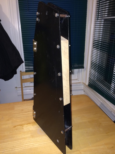
If you want, I can post pictures of my rudder headstock, but keep in mind mine has been modified to stiffen up with that teak spacer replacing many of the riveted spacer sleeves. (If you did not realize, the two black headstock side plates are separated by SS tube spacers, which are riveted in place. Eventually, the rivets will loosen, allowing for independent plate movement.)
If you want, I can post pictures of my rudder headstock, but keep in mind mine has been modified to stiffen up with that teak spacer replacing many of the riveted spacer sleeves. (If you did not realize, the two black headstock side plates are separated by SS tube spacers, which are riveted in place. Eventually, the rivets will loosen, allowing for independent plate movement.)

I just got done with a complete rebuild of my 222 rudder and headstock. I changed the pivot point and reshaped the upper part of the rudder to allow the whole rudder to come out of the water. The downhaul line is run through a block attached to a padeye on the tiller. I don't have any pictures of it so I made a cad drawing. The blue line represents the downhaul. The uphaul line runs through a block tied to the rudder to give a 2:1 advantage for lifting, as shown in the photo. I love how the rudder goes up and down now, before it was a real pain!
Joe


Joe
Ok, Bob, here are pictures of my modified rudder. Looks like Joe beat me to some pix of his. It looks pretty sweet. I see that I over-engineered my headstock, and the $80 piece of teak makes it heavy as crap. I also added an uphaul line, because originally, it did not have one. I must push in the top of the foil to start the blade coming up, and then the uphaul works. It does not get the blade all the way out of the water, but most of the way. I keep the blade up and cocked to one side. I want it out of the water so tiny wave action doesn't work the pintles in the gudgeons and introduce even more slop into them. But I fix the tiller off to the side so that the blade isn't sticking out from the end of my slip. I've heard far too many stories of incompetents at my marina ping-ponging down the slipway off the motors and transoms of boats.
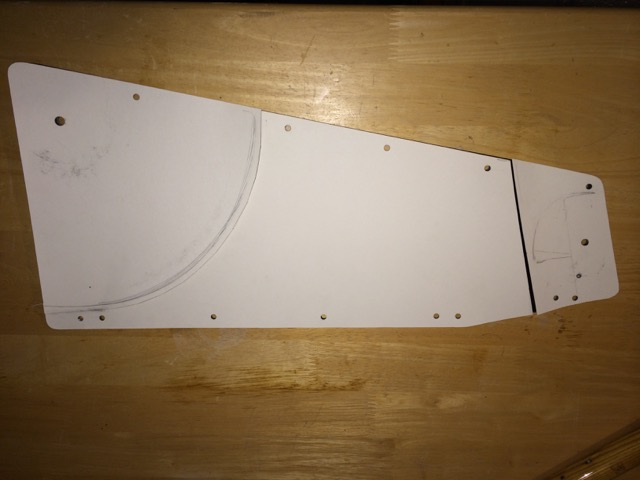
First, we have the template of my side plates, where I tried to approximate the arc of the blade head, and also how low to cut the spacer to allow the tiller to pivot up for more lounging room in the cockpit. I finally decided a straight cut off spacer would be better than trying to notch the arc of the heel of the tiller, thus collecting rainwater.
Next we have the massive teak block and tiller in position on a side plate. I painted the side plates with epoxy suspension paint sourced at a local auto parts store. Holding up well to 3 seasons of fresh water.
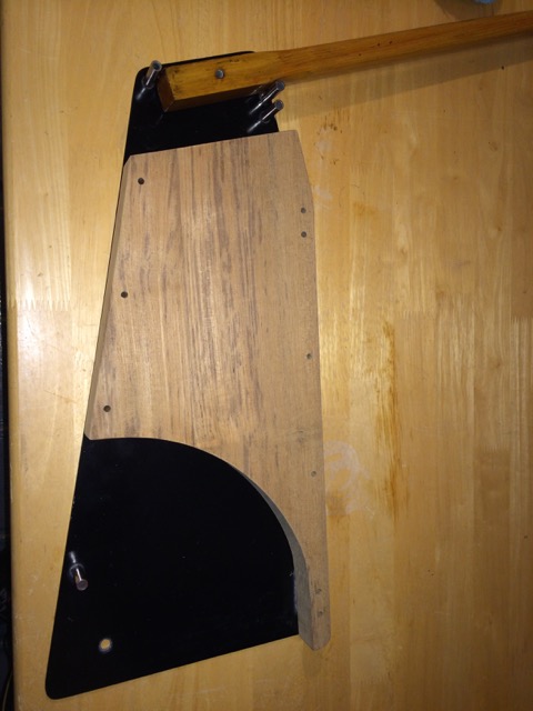
Next pic shows how much room I needed for pivoting tiller action:
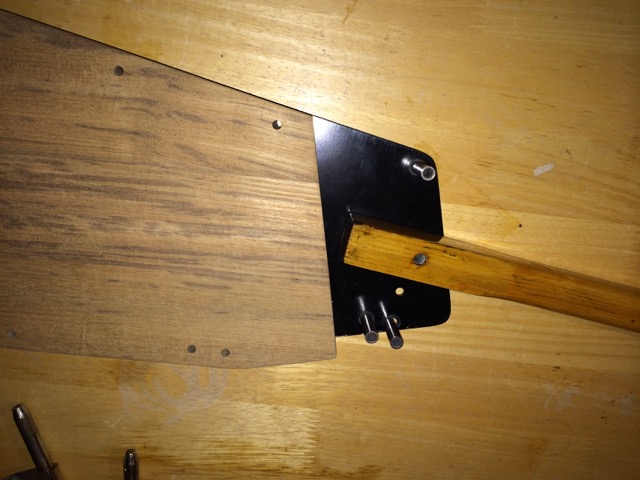
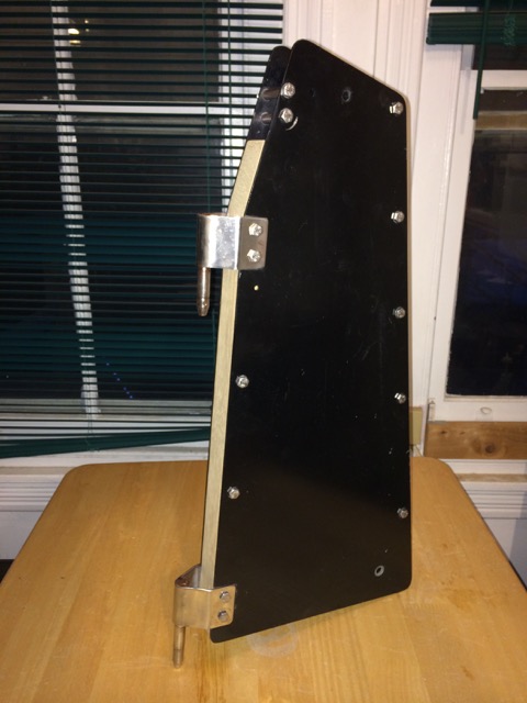
And here are pix of the front and rear of the assembly using 1/4-20 316 SS bolts and some of the original spacer sleeves. She may be on fresh water, but I generally only use 316 SS fasteners due to that over-engineering problem I have. Hey, someday she may see salt water!
I did discover that once I had everything installed, the downhaul line did not work at all. So I cut a notch in the end of the arc of teak, drilled a hole through the side and inserted the smooth shank of a 1/4-20 bolt as an axle. I found a very small sheave from Holt Allen that fit over the axle. The downhaul line now runs in this slot over the sheave. I think I also install a very small eye strap over the very tip so that the line would not jump out of the slot off the sheave. It has worked so well, this is the first time I've thought of it in 2 or 3 seasons! Also, something changed in the arc of the blade, forcing it aftwards just a smidge. It was enough to make the helm feel heavy, and necessitated me moving the rake of the mast to achieve optimum weather helm of 3º or so. The following pix are of the rudder on the boat, with the rudder raised. Note that the design did not have any uphaul line (the white one in pix.) Bringing it over the top of the tiller pulls on the cleat on the top of the tiller in such a way that the tiller does not pivot up. The downhaul line is the blue one, and is fixed inside the rudder head by a factory hole in the leading edge of the head, into a coin sized factory recess which I filled with 3M 4000 or such that I had on hand.
A view down the forward edge of the headstock. Note that small, triangular shaped Holt Allen fairleads are set inside the pintle brackets.
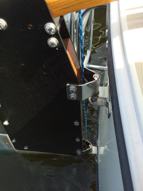
This shot shows the up haul coming through the fairleads and pintle brackets, to the small Harken cheek block and then forward on the tiller.
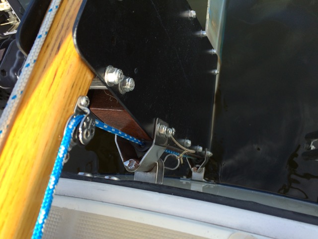
And finally, a look down the side of the tiller, showing the auto-releasing Clam Cleat and the cheek block:
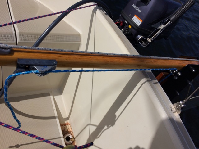
Again, the white with blue tracer is the uphaul line, and the purple with pink/yellow/blue tracer is the line for my Wave Front Marine Tiller Clutch. Can't sail solo without that! The clam cleats on the top of the transom coaming, just out of view, are also used with a length of utility cord cow hitched over the tiller cover to hold the tiller arm off to starboard, kicking the raised rudder blade off to the side. I suppose if someone's going straight into the stern of my boat from the slipway, I'm screwed either way. Oh, well, the captains on my slipway have been reasonably competent so far.
First, we have the template of my side plates, where I tried to approximate the arc of the blade head, and also how low to cut the spacer to allow the tiller to pivot up for more lounging room in the cockpit. I finally decided a straight cut off spacer would be better than trying to notch the arc of the heel of the tiller, thus collecting rainwater.
Next we have the massive teak block and tiller in position on a side plate. I painted the side plates with epoxy suspension paint sourced at a local auto parts store. Holding up well to 3 seasons of fresh water.
Next pic shows how much room I needed for pivoting tiller action:
And here are pix of the front and rear of the assembly using 1/4-20 316 SS bolts and some of the original spacer sleeves. She may be on fresh water, but I generally only use 316 SS fasteners due to that over-engineering problem I have. Hey, someday she may see salt water!
I did discover that once I had everything installed, the downhaul line did not work at all. So I cut a notch in the end of the arc of teak, drilled a hole through the side and inserted the smooth shank of a 1/4-20 bolt as an axle. I found a very small sheave from Holt Allen that fit over the axle. The downhaul line now runs in this slot over the sheave. I think I also install a very small eye strap over the very tip so that the line would not jump out of the slot off the sheave. It has worked so well, this is the first time I've thought of it in 2 or 3 seasons! Also, something changed in the arc of the blade, forcing it aftwards just a smidge. It was enough to make the helm feel heavy, and necessitated me moving the rake of the mast to achieve optimum weather helm of 3º or so. The following pix are of the rudder on the boat, with the rudder raised. Note that the design did not have any uphaul line (the white one in pix.) Bringing it over the top of the tiller pulls on the cleat on the top of the tiller in such a way that the tiller does not pivot up. The downhaul line is the blue one, and is fixed inside the rudder head by a factory hole in the leading edge of the head, into a coin sized factory recess which I filled with 3M 4000 or such that I had on hand.
A view down the forward edge of the headstock. Note that small, triangular shaped Holt Allen fairleads are set inside the pintle brackets.
This shot shows the up haul coming through the fairleads and pintle brackets, to the small Harken cheek block and then forward on the tiller.
And finally, a look down the side of the tiller, showing the auto-releasing Clam Cleat and the cheek block:
Again, the white with blue tracer is the uphaul line, and the purple with pink/yellow/blue tracer is the line for my Wave Front Marine Tiller Clutch. Can't sail solo without that! The clam cleats on the top of the transom coaming, just out of view, are also used with a length of utility cord cow hitched over the tiller cover to hold the tiller arm off to starboard, kicking the raised rudder blade off to the side. I suppose if someone's going straight into the stern of my boat from the slipway, I'm screwed either way. Oh, well, the captains on my slipway have been reasonably competent so far.
Ok, Bob, here are pictures of my modified rudder. Looks like Joe beat me to some pix of his. It looks pretty sweet. I see that I over-engineered my headstock, and the $80 piece of teak makes it heavy as crap. I also added an uphaul line, because originally, it did not have one. I must push in the top of the foil to start the blade coming up, and then the uphaul works. It does not get the blade all the way out of the water, but most of the way. I keep the blade up and cocked to one side. I want it out of the water so tiny wave action doesn't work the pintles in the gudgeons and introduce even more slop into them. But I fix the tiller off to the side so that the blade isn't sticking out from the end of my slip. I've heard far too many stories of incompetents at my marina ping-ponging down the slipway off the motors and transoms of boats.
First, we have the template of my side plates, where I tried to approximate the arc of the blade head, and also how low to cut the spacer to allow the tiller to pivot up for more lounging room in the cockpit. I finally decided a straight cut off spacer would be better than trying to notch the arc of the heel of the tiller, thus collecting rainwater.
View attachment 128519
Next we have the massive teak block and tiller in position on a side plate. I painted the side plates with epoxy suspension paint sourced at a local auto parts store. Holding up well to 3 seasons of fresh water.
View attachment 128520
Next pic shows how much room I needed for pivoting tiller action:
View attachment 128521
And here are pix of the front and rear of the assembly using 1/4-20 316 SS bolts and some of the original spacer sleeves. She may be on fresh water, but I generally only use 316 SS fasteners due to that over-engineering problem I have. Hey, someday she may see salt water!
View attachment 128522
View attachment 128523
I did discover that once I had everything installed, the downhaul line did not work at all. So I cut a notch in the end of the arc of teak, drilled a hole through the side and inserted the smooth shank of a 1/4-20 bolt as an axle. I found a very small sheave from Holt Allen that fit over the axle. The downhaul line now runs in this slot over the sheave. I think I also install a very small eye strap over the very tip so that the line would not jump out of the slot off the sheave. It has worked so well, this is the first time I've thought of it in 2 or 3 seasons! Also, something changed in the arc of the blade, forcing it aftwards just a smidge. It was enough to make the helm feel heavy, and necessitated me moving the rake of the mast to achieve optimum weather helm of 3º or so. The following pix are of the rudder on the boat, with the rudder raised. Note that the design did not have any uphaul line (the white one in pix.) Bringing it over the top of the tiller pulls on the cleat on the top of the tiller in such a way that the tiller does not pivot up. The downhaul line is the blue one, and is fixed inside the rudder head by a factory hole in the leading edge of the head, into a coin sized factory recess which I filled with 3M 4000 or such that I had on hand.
A view down the forward edge of the headstock. Note that small, triangular shaped Holt Allen fairleads are set inside the pintle brackets.
View attachment 128525
This shot shows the up haul coming through the fairleads and pintle brackets, to the small Harken cheek block and then forward on the tiller.
View attachment 128526
And finally, a look down the side of the tiller, showing the auto-releasing Clam Cleat and the cheek block:
View attachment 128527
Again, the white with blue tracer is the uphaul line, and the purple with pink/yellow/blue tracer is the line for my Wave Front Marine Tiller Clutch. Can't sail solo without that! The clam cleats on the top of the transom coaming, just out of view, are also used with a length of utility cord cow hitched over the tiller cover to hold the tiller arm off to starboard, kicking the raised rudder blade off to the side. I suppose if someone's going straight into the stern of my boat from the slipway, I'm screwed either way. Oh, well, the captains on my slipway have been reasonably competent so far.
SUPER JOB! I rebuilt mine using heaver plate w/ bushings but orig. otherwise. No flex but blade would slowly creep up at times. Most of the time Im in deep water so I put a thru pin in. Its easy to remove to enter unknowen areas. Of course I might forget but then prob. pin could be removed and rudder lifted w/ out much troub.I just got done with a complete rebuild of my 222 rudder and headstock. I changed the pivot point and reshaped the upper part of the rudder to allow the whole rudder to come out of the water. The downhaul line is run through a block attached to a padeye on the tiller. I don't have any pictures of it so I made a cad drawing. The blue line represents the downhaul. The uphaul line runs through a block tied to the rudder to give a 2:1 advantage for lifting, as shown in the photo. I love how the rudder goes up and down now, before it was a real pain!
Joe
View attachment 128513View attachment 128514
The rudder on my 222 keeps drifting up as I sail. It gradually becomes difficult to steer and I have to take a boat hook and push it down. I have the line from the curve of the rudder as tight as I can get it. Any suggestions?