I finally got around to connecting my solar panel. It charged a battery that was roughly 50% discharged to fully charged in 24 hours. But now the voltage is always showing 13-14 volts. Is this expected when it's maintaining? I'm a bit concerned that it's overcharging my brand new batteries.
Solar Voltage
- Thread starter Project_Mayhem
- Start date
Is this expected when it's maintaining?
PM,It has a PWM controller
Dare I suggest RTFM?
")
The controller should hold lead acid batteries in the low/mid 13’s once they’re full. That’s the float stage of charging. The specific voltage target depends on the battery type, and there may be settings on the controller to match its float voltage with what’s ideal for your batteries.
Here is some stuff:
Calculating Proper Charge Settings for Rolls Flooded Lead-Acid Batteries : Technical Support (rollsbattery.com)
Sounds like the controller is doing its job.
Calculating Proper Charge Settings for Rolls Flooded Lead-Acid Batteries : Technical Support (rollsbattery.com)
Sounds like the controller is doing its job.
Start with a quality controller... Victron, Morningstar etc. (eg: a real company that knows what they are doing in the solar space.. many of these cheap controllers can definitely ruin batteries..It's in broken english
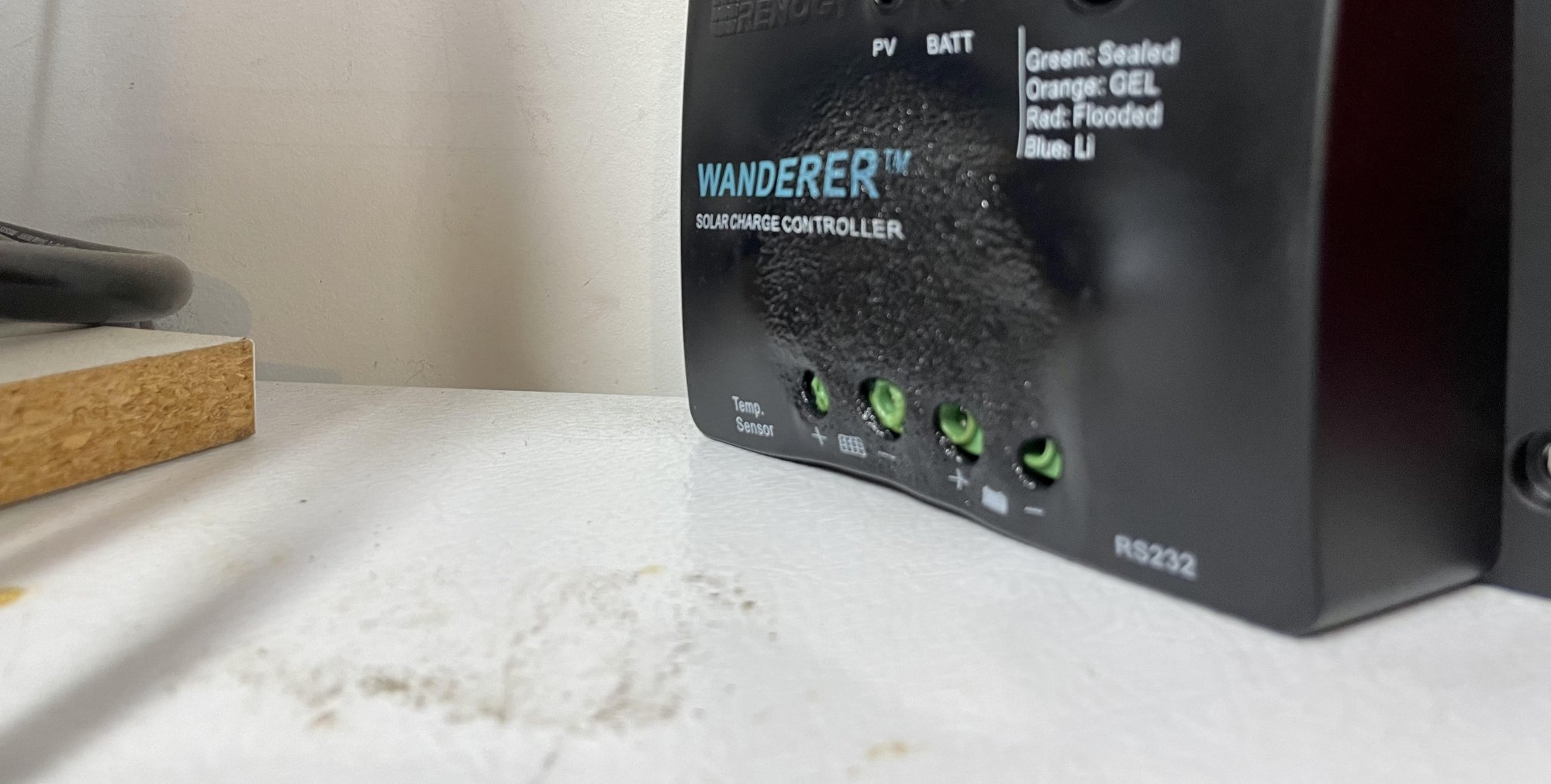
Almost lost my boat when I chose a budget controller a Renogy. I have a Victron now. Renogy never got back to me on this almost fire.. be quite careful with cheap solar products. I learned this the wrong way
Last edited:
I have one of these lying around but not connected quite yet. Did you have proper sized fuses on the input and output side?Almost lost my boat when I chose a budget controller a Renogy. I have a Victron now. Renogy never got back to me on this almost fire.. be quite careful with cheap solar products. I learned this the wrong wayView attachment 207843
You really shouldn’t need fuses on the input side of a charge controller. The input side comes from the PV panels, which can only put out a specific amount of energy. The wire should be sized to handle that amperage. On the output side you should have a fuse, but at the battery end of the cables, since the battery is the potential source of excessive current.I have one of these lying around but not connected quite yet. Did you have proper sized fuses on the input and output side?
If the controller has a malfunction there's a chance that the input or output side could short. I'm guessing that your solar panel wouldn't be too happy about that. Besides, it's a good idea to protect your wiring with a fuseYou really shouldn’t need fuses on the input side of a charge controller. The input side comes from the PV panels, which can only put out a specific amount of energy. The wire should be sized to handle that amperage. On the output side you should have a fuse, but at the battery end of the cables, since the battery is the potential source of excessive current.
I found a couple of Morningstar controllers for a very reasonable price. Would it be better to have a charge circuit for each battery (whether it's two controllers or a dual batt model) or run both batteries, which are the same age/model, as a single bank?Start with a quality controller... Victron, Morningstar etc. (eg: a real company that knows what they are doing in the solar space.. many of these cheap controllers can definitely ruin batteries..
https://www.amazon.com/Morningstar-Controller-Batteries-Built-Diagnostics/dp/B007NNMEU6
https://www.amazon.com/Morningstar-SHS-6-Solar-Controller-Watts/dp/B007NZLC66
This boat is used 2-3 times a week as a day sailor. Only power draw while in use is the bilge pump, small Class D audio amp and engine starter. Engine starts up pretty quickly
Solar panels are ok with being shorted, provided that they’re single panels or wired in series. Panels in parallel could short each other and should therefore be fused.If the controller has a malfunction there's a chance that the input or output side could short. I'm guessing that your solar panel wouldn't be too happy about that. Besides, it's a good idea to protect your wiring with a fuse
Citation, with someone much smarter about marine electrical systems than me explaining the requirements:

Battery side was 20A panel side 10A. no blown fuses..Though my ABYC electrician said I don't need one on the solar side only one 100W panel and 10AWG wire...I am getting way better charging with the Victron than I did with the Renogy.I have one of these lying around but not connected quite yet. Did you have proper sized fuses on the input and output side?
Battery side was 20A panel side 10A. no blown fuses..Though my ABYC electrician said I don't need one on the solar side only one 100W panel and 10AWG wire...I am getting way better charging with the Victron than I did with the Renogy.
I have nearly the same setup as you did, right down to the wire guage
I found a pair of Morningstar Sunsaver SS-6L controllers on ebay for a meager $40. It's within spec for the 100w panel I have. I know MPPT is more efficient but this current system has far exceeded my expectation and needs. Thanks for everyone's help!
It is important to remember the voltage coming off the panels is in the 20-28v range. When sizing wire from the panel to the controller use the 24v tables.
Victron controllers have an ATC fuse the, I believe to protect the panel from excessive current back feeding into them. From the DC+ bus there should be a fuse as close to the bus bar as possible to procte the wire from a short. The fuse needs to be larger than the controller's output.
Victron controllers have an ATC fuse the, I believe to protect the panel from excessive current back feeding into them. From the DC+ bus there should be a fuse as close to the bus bar as possible to procte the wire from a short. The fuse needs to be larger than the controller's output.
What? The controller is the power source. Fuse it at the output.On the output side you should have a fuse, but at the battery end of the cables, since the battery is the potential source of excessive current.
The controller can only output as much as its internal components will let it, which is its rating. The cables should be sized to handle the maximum output current that can come from the controller. The batteries can output hundreds of amps, far more than the cables can handle. That’s why you fuse at the battery end of the cable.What? The controller is the power source. Fuse it at the output.
The fuses are protecting the wires from catching fire in a dead short situation from the battery.What? The controller is the power source. Fuse it at the output.
I have a Victron Energy datasheet up from a previous post about DC-DC chargers. The fundamentals are the same here. Notice the location of the two fuses. A fuse is connected to the batteries, for safety, every time a wired connection is made to the batteries. Any benefits to the electronic device from fusing are secondary to the primary purpose of the fuses, which is to protect the wires from melting and starting a fire, should a short occur.