High SWR on VHF Cabling/Antenna

Sep 22, 2021
284
Hunter 41AC 0 Portland, OR
I recently installed an Em-Trak B951 AIS tranceiver, replacing the Em-Trak R100 AIS receiver that was on the boat when we bought it. The installation went fairly smoothly but when I powered it up I shortly got an alarm from the AIS unit indicating that the Standing Wave Ratio was too high.

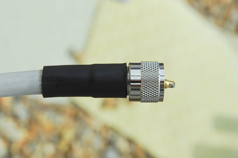
Using a Shakespeare ART-3 SWR meter, I confirmed that the SWR from the VHF radio's perspective was, in fact, way too high (nearly off the scale). The same high reading was found connecting the antenna cable directly to the VHF radio (eliminating the antenna splitter). I was able to get a 50 ohm dummy load and I installed it at the end of the cable run from the nav station to the base of the mast. That produced a very good SWR reading both with and without the antenna splitter and the AIS transceiver operated without an alarm (although no target information was received, of course).

These tests lead me to conclude that the problem is either in the coax run up the mast, the antenna atop the mast or the connection of the antenna to the coax at the top of the mast. My next test is to go up the mast and install the dummy load in place of the antenna. That should show if the coax run up the mast is OK or not. If it is, the antenna would be the only culprit left.

I would be interested if anyone else has had such a problem and, if so, what the problem was found to be.
 
Jan 11, 2014
12,749
Sabre 362 113 Fair Haven, NY
Coax cable has a life span, especially when it is exposed to the elements. Additionally if the connections are not well sealed to the elements, then corrosion can occur and increase the SWR.

Last year I replaced the RG-8 (skinny coax) with Times Microwave LMR Ultraflex 50 ohm coax and saw a notable improvement in reception.

My suggestion is to replace the cable with proper fittings and seal the cable connections at the masthead with a self-amalgamating tape. See the article below for more information.

 
  • Helpful
Likes: jssailem
Sep 25, 2008
7,345
Alden 50 Sarasota, Florida
i infer you have a VHF antenna fed through a splitter. Keep in mind AIS transmits on/around 162 MHz vs the marine radio frequency range of 150+/- MHz. If in fact it is a generic marine VHF antenna, I would expect a significant mismatch because of the disparity in resonant frequency. In other words, there may be nothing wrong with either your coax, the connectors or the antenna which isn’t designed to operate at AIS frequencies.
having said all that, it’s always good routine maintenance practice to periodically inspect the coax and all connections.
 
Sep 22, 2021
284
Hunter 41AC 0 Portland, OR
Thanks. I am aware of the frequency difference and I have a replacement antenna that is compatible with both AIS and marine VHF frequencies. However, in my earlier tests I measured the SWR with the VHF radio transmitting over the existing in-mast cable and the currently-installed antenna. It was really bad, nearly off the scale. That points to a problem with the existing cable or antenna. I'll figure that out by putting the dummy load at the top of the mast and measuring the SWR with the VHF radio transmitting. Based on the result, I will replace the in-mast coax if necessary.

I did connect my new AIS-compatible antenna to the cable at the base of the mast. The SWR that I measured with the VHF radio transmission was well within the acceptable limits and the AIS transceiver operated without generating an alarm. So, I'm fairly confident that everything from the base of the mast back to the nav station is in good working order.
 

jssailem

SBO Weather and Forecasting Forum Jim & John
Oct 22, 2014
22,818
CAL 35 Cruiser #21 moored EVERETT WA
Don.
US VHF FREQUENCY RANGE. 156.050 Channel 01A to 162.55 NOAA Weather Channel 1

AIS
Primary Channel A - 161.975 MHz

Primary Channel B - 162.025 MHz

Vesper offered a tuned antenna and powered AIS/VHF splitter. Been working on my boat since 2016.
 
Feb 17, 2006
5,274
Lancer 27PS MCB Camp Pendleton KF6BL
I think you are on the right track. At least you are not chasing rabbits. So far you best plan of action is to get the dummy load to the top of the mast. At least there you will either eliminate the cable run or have to replace the cable run. Connectors are always a culprit. I was lucky to find on my radio the antenna cable connector was not soldered correctly. So that was an easy fix. But you have an unidentified issue at a location far, far away. LOL (not laughing at you, but with you).

I hope it is just a simple connector replacement and not a new cable pull. But you will shortly see. Be safe going up that mast.

It seems like you have a grasp in what you are doing. In this thread I talk about some reasonably priced test gear that could help with your problem. One of them, the NanoVNA would tell you where the problem was located.

Good luck!
 
  • Helpful
Likes: jssailem
Sep 22, 2021
284
Hunter 41AC 0 Portland, OR
Brian D, thanks for the information on the NanoVNA, I used something similar (but more primitive) in my undergraduate Electrical Engineering classes to do TDR (Time Domain Reflectometry) measurements on transmission lines. Although i did go on to do graduate work in EE, I specialized in digital rather than analog electronics.
 
  • Like
Likes: Brian D
Sep 22, 2021
284
Hunter 41AC 0 Portland, OR
I went up the mast today with a buddy (who is a sailer and a rock climber) manning the winch. After installing a dummy load at the top end of the VHF coax, the SWR meter indicated a much-too-high SWR. The next task, then, is to replace the coax.

While I was up there, I greased the upper in-mast furler bearing and we pulled a new messenger line to replace the aging one that was present. I re-purposed part of the replaced messenger line (that was inside the mast) as a starboard flag halyard - the eye was present on the lower starboard spreader but there was no line running through it.

For ascending, the newly replaced topping lift was used for the main line and the newly replaced spinnaker halyard was used as a safety line. When the Prusik loop on the safety got to the upper spinnaker halyard block, I used another short line with a bowline at each end to allow continued ascent to the top of the mast. Of course, this would result in a longer drop in case of failure but it was still a serviceable backup. Happily, the backup was not put to the test.

Ascending-the-Mast.jpg
 

jssailem

SBO Weather and Forecasting Forum Jim & John
Oct 22, 2014
22,818
CAL 35 Cruiser #21 moored EVERETT WA
It is not the drop that worries me. It is the sudden stop. :yikes:
 
Feb 17, 2006
5,274
Lancer 27PS MCB Camp Pendleton KF6BL
I am curious to know; does the RF cable run continuously from the AIS to the top of the mast, or, is there a barrel connector between the runs.
 
Sep 22, 2021
284
Hunter 41AC 0 Portland, OR
There is a connection below the base of the mast. It is accessible via a plate on the ceiling in the forward cabin. I tested the cable run between the nav station and the base of the mast by putting the dummy load on the end of that cable at the base of the mast and the SWR was pretty close to 1.0 indicating that that section of cable is OK.