Getting cables to reach bus bar

May 17, 2004
5,032
Beneteau Oceanis 37 Havre de Grace
One of my winter projects will be to replace our Beneteau master ground interrupt switch with a ground bus bar and add a Victron Smart Shunt. I was looking at the current cable configuration and I’m not sure where I should add the bus bar so all the cables can reach it. There are three 2/0 ground cables coming into the switch from aft (engine bank, house bank, and engine), and three 2/0 cables running forward (thruster battery, windlass, and house loads).

1638625845770.jpeg


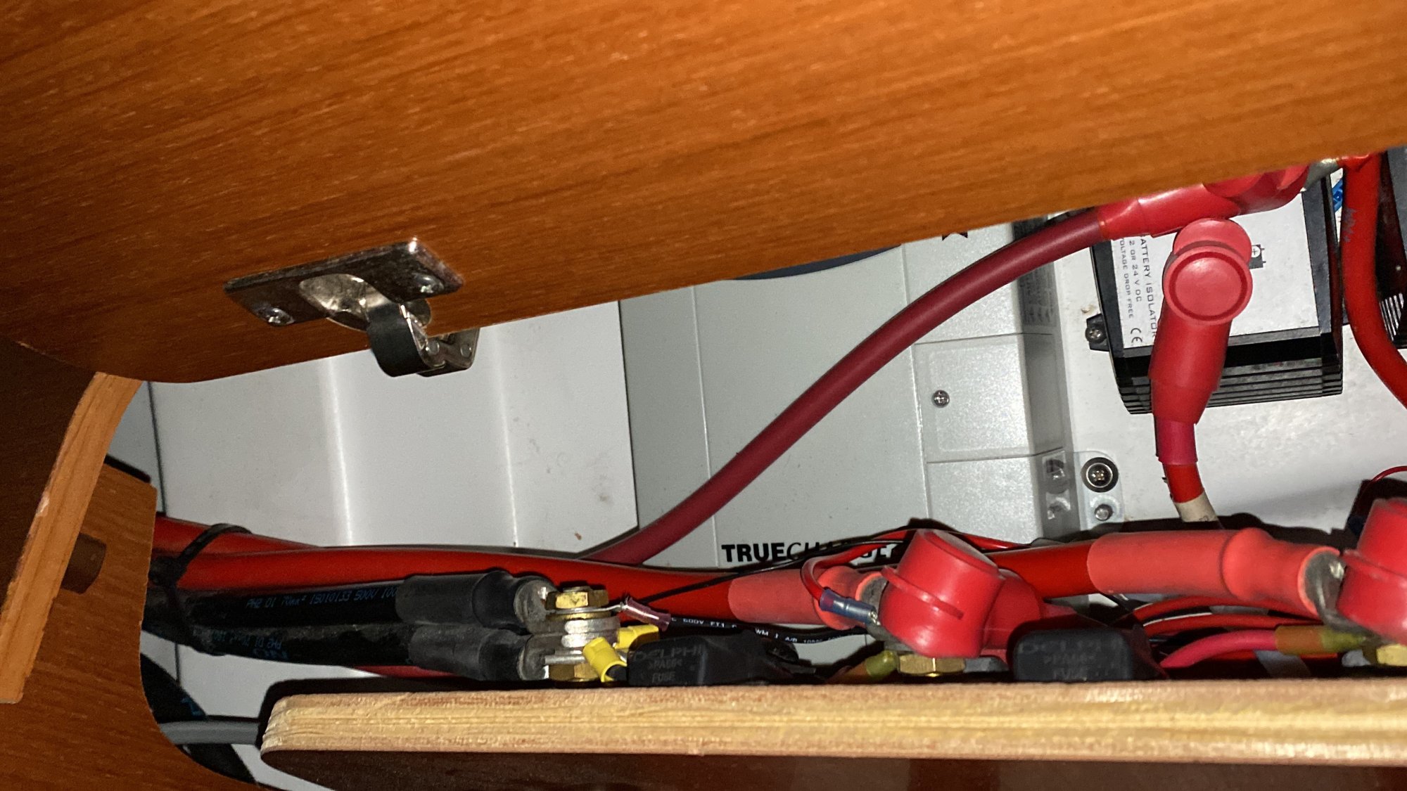
There is a hull surface just behind the current switch where I think I could fit the bus and shunt. My problem is that the 2/0 cable to the thruster battery looks like it’s about 6” too short to get to that surface. Re-running the cable through the whole length of the boat is not feasible. All of the other cables are too short to reach anywhere in front of the switch. Does anyone have creative suggestions for putting the bus where I want? Should I try to fit a 2 post bus somewhere the thruster cable can reach with an extra extension to the main bus?
 
Oct 22, 2014
20,995
CAL 35 Cruiser #21 moored EVERETT WA
David, this sounds like a good project. I am assuming you plan to remove the Ground Interrupt Switch.

Not knowing your complete layout, the image provides a view of multiple Black (negative) wires stacked on a post. I assume that is the post for the switch that is going away. You intend to connect those wires to a busbar and then connect the busbar to the negative lead on your battery. This connection will need to be of proper gauge wire to handle the current of the system over the length of the run. The Victron shunt is connected between the battery and the Negative Buss Bar. All DC current flows through the Victron shunt. Necessary for the shunt to measure the current used.

My confusion comes from not understanding the Thruster reaching comment. Is the thruster negative line not a part of the image?

There would be no problem to have a separate bus for the short Thruster wire. Just remember that the additional 6 inches is an add to the total wire system for the thruster. You will want to assure minimal voltage drop. Verify the cable gauge needed to handle the thruster load maintaining the voltage needs. It will be at least the gauge of the current wires. Assume a .5% drop for the extra busbar.
 
May 17, 2004
5,032
Beneteau Oceanis 37 Havre de Grace
I am assuming you plan to remove the Ground Interrupt Switch
I'm going to repurpose it as an emergency cut-over switch for the engine and house banks. Maine Sail has documented that configuration for Beneteaus with their three on/off switch configuration.
the image provides a view of multiple Black (negative) wires stacked on a post. I assume that is the post for the switch that is going away. You intend to connect those wires to a busbar and then connect the busbar to the negative lead on your battery.
The post you see with the stacked black wires is the input to the existing switch. The output post is hidden below it. The input post has the ground wires to each of the 3 banks (house, engine, thruster), plus the ground from the charger and ground for the always-on bilge pump. My plan is to put everything that's currently on both the input and output side of the switch onto a bus. The cable between the house bank and the bus will have the shunt inserted.

My confusion comes from not understanding the Thruster reaching comment. Is the thruster negative line not a part of the image?
The thruster cable is one of the ones on that top post. It's hard to see because it's pretty well hidden behind the black fuse holder. My plan is to put the main bus bar on the fiberglass area on the left of the picture, but the thruster cable comes in from the right of the picture and was cut just long enough to reach the switch.

There would be no problem to have a separate bus for the short Thruster wire. Just remember that the additional 6 inches is an add to the total wire system for the thruster. You will want to assure minimal voltage drop. Verify the cable gauge needed to handle the thruster load maintaining the voltage needs. It will be at least the gauge of the current wires. Assume a .5% drop for the extra busbar.
I'll need to do the math if a bus bar would add 0.5% drop. The cable already runs about 35' to the thruster bank under the V-berth, so I don't think the extra 6" will be significant. That cable doesn't really power the thruster, it just charges the thruster bank from the alternator and/or charger, so it's not like it doesn't need to carry the full thruster amperage, just the charge amperage that the battery needs. Good points for me to consider; Thanks!
 
  • Like
Likes: jssailem
Nov 30, 2020
79
Macgregor 22 Dania, FL
The "easy" way to extend those cables is to get a same-diameter battery cable the length you need. Then bolt the two together with stainless or bronze bolts, nuts and lockwashers. Tighten up good and tape with rubber tape and then vinyl tape. Finish with a coat of clear lacquer so the tape doesn't come loose.
Chip V.
 
May 17, 2004
5,032
Beneteau Oceanis 37 Havre de Grace
The "easy" way to extend those cables is to get a same-diameter battery cable the length you need. Then bolt the two together with stainless or bronze bolts, nuts and lockwashers. Tighten up good and tape with rubber tape and then vinyl tape. Finish with a coat of clear lacquer so the tape doesn't come loose.
Chip V.
Thanks. If joining two cables with a bolt is considered good practice it certainly will be the easiest.

I should add that I’ve measured a voltage drop across the switch of 15-150 mV at just 10 A depending on how the switch contacts sit. So replacing the switch with a bus bar or two should hopefully not be any worse than that.
 
  • Like
Likes: jssailem
May 17, 2004
5,032
Beneteau Oceanis 37 Havre de Grace
You can use a power post to add an extension to the thruster cable. Or instead of a negative ground, use a power post. These are not current rated because each cable is stacked on to the next, so no current runs through a bar.

Nice. I didn’t know a single post like that was a thing. I should be able to fit that somewhere in the cabinet within reach of the existing cable. Should be just the ticket. :)
 

Tom J

.
Sep 30, 2008
2,301
Catalina 310 Quincy, MA
Thanks. If joining two cables with a bolt is considered good practice it certainly will be the easiest.
Back in the day, one of the senior mechanics would have sent me to find a cable stretcher.:huh: We did find at one point that we could save a full day's labor if we cut the cables to the motors we were working on, and then spliced them with bolts and covered those with heat shrink. These were 6/0 cables carrying up to 600 amps of current at 600 volts, and the manufacturer okayed this as an acceptable practice.
That being said, I would prefer the post to hold the cable in place.
 
Jan 11, 2014
11,323
Sabre 362 113 Fair Haven, NY
Back in the day, one of the senior mechanics would have sent me to find a cable stretcher.:huh: We did find at one point that we could save a full day's labor if we cut the cables to the motors we were working on, and then spliced them with bolts and covered those with heat shrink. These were 6/0 cables carrying up to 600 amps of current at 600 volts, and the manufacturer okayed this as an acceptable practice.
That being said, I would prefer the post to hold the cable in place.
When running cables, it is often best to measure once and cut twice. :)
 

RoyS

.
Jun 3, 2012
1,739
Hunter 33 Steamboat Wharf, Hull, MA
You can purchase cable crimp couplings. Crimp with the proper tool and tape over. There will be no voltage drop.
 
  • Like
Likes: Tom J
Oct 26, 2008
6,045
Catalina 320 Barnegat, NJ
I used a Blue Sea power post for a similar situation, just as Dave suggests. Simple & secure.
 

Tom J

.
Sep 30, 2008
2,301
Catalina 310 Quincy, MA
You can purchase cable crimp couplings. Crimp with the proper tool and tape over. There will be no voltage drop.
We used the crimp couplings when repairing cables. We only used the bolt connectors because we would be disconnecting the cables again when the motors were replaced.