Check my wiring diagram?

Beth G

.
Jun 2, 2023
15
Capital Yachts Neptune 24 Lake Ontario
Hi there! New boat owner here...we inherited our sailboat, and are redoing the wiring. I have made a wiring diagram, it's at the bottom of this, and am hoping to get some input on it. To help, here's a basic description of my systems:

1) The "positive" side of the DC system, going from batteries to the components:
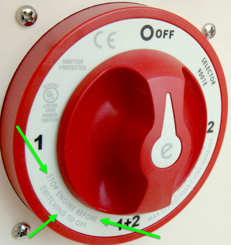
  • a deep cycle house battery and a cranking battery for the outboard motor, utilizing a 1/2/both switch.
  • VHF radio, marine stereo, and switch panel connect to the 1/2/both switch (with a 50 Amp fuse before them, in line fuses for the radio and stereo, and my switch panel has integrated circuit breakers - yay no fuse box!)
  • Bilge system connects straight to the house battery, so it will run in automatic mode even if the 1/2/both switch is set to off. See, I'm learning!
2) For the negative (ground) side of the DC:
  • The house battery negatives are connected together.
  • I have the radio, stereo, and switch panel negatives combining in a negative "switch bus".
  • I belive the "common ground" I've created, hopefully without a ground loop is, the "ground bus" - the engine, batteries (via one of their negative terminals), bilge pump, and switch bus all connect to that bus.
3) AC system is very basic, and I've not drawn it other than the takeoff from its ground point: I have a shore power hookup that supplies 2 110V outlets, one of which has my battery charger plugged into it. The ground from this system will be connected to the DC ground to maintain one common ground.

My questions:
1) did I screw anything up?
2) I'm assuming that, since my breaker for everything being powered by the 1/2/off switch is 50A I need a cable gauge to safely carry that voltage from the switch bus to the DC ground bus?
3) is 50A massively big for the switch panel, VHF, stereo circuit? We could have bought a 30, but weren't sure and didn't want to undersize it.
4) what size ground wire would you use to hook the batteries up to the DC ground bus, and the DC ground bus to the engine? We are using 6 gauge positive cables to connect the batteries to the 1/2/off switch, it's less that 2' away from one of the batteries and 1' from the other one.
5) my husband feels we should connect the negative bilge pump wire direct to the battery instead of to the DC bus. Or, put the switch bus directly on the batteries as well, and connect the battery and AC ground straight to the engine, thus eliminating the ground bus. I'm not sure why, but that's making me leery. What are your thoughts?
20230602_210232.jpg
 
  • Like
Likes: jviss

jssailem

SBO Weather and Forecasting Forum Jim & John
Oct 22, 2014
22,261
CAL 35 Cruiser #21 moored EVERETT WA
Beth.
It will take some time to consider all that you have submitted. I like to learn the details. One of the best resources on the web is MaineSail. He has his own website. It is like a library of electrical knowledge. I’d encourage you to look at this stuff and find your answers.
One place to start is with his work on Fuses.
MaineSail has through the years created this treasure of ideas. Right now he could use a hand. If you find he helps you keep your boat and crew safe, maybe you can make a donation to keep his library alive.
 

jssailem

SBO Weather and Forecasting Forum Jim & John
Oct 22, 2014
22,261
CAL 35 Cruiser #21 moored EVERETT WA
Here are a couple more gems.


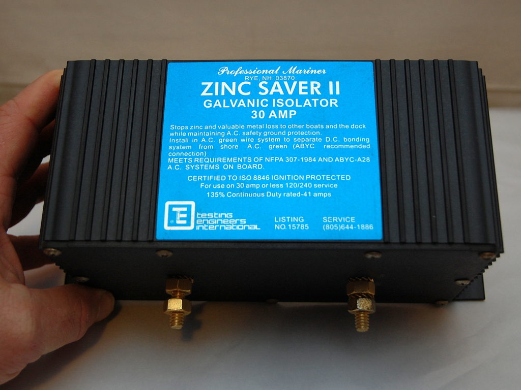
Your AC ground goes back to the shore power box. The use of a Galvanic Isolator is an essential safety system.
 
Jan 11, 2014
12,320
Sabre 362 113 Fair Haven, NY
A few quick comments.

The house and start batteries need to be fuse within 7 inches of the battery. A MRBF (marine rated battery fuse) is ideal for this purpose.

The AC ground wire does need to be connected to the outboard. When plugged into AC the OB will be out of the water.

The only purpose for the DC- to be attached to the OB is the starter. Do not rely on the charing circuit from the OB to keep the batteries fully charged. The out put is minimal and unregulated, i.e., the output current will vary with engine speed with full output only at high speed.

Connect all of the "always on" devices to a positive bus bar or fuse box. Keep the number of wires connected to the battery terminals to a minimum, less than 4.

The VHF and Stereo can be connected to the panel with circuit breakers.

What is the purpose of the DC- from the switch panel?

How are you going to charge the batteries?

As for fusing and wire gauge. Calculate the max current draw for the panel, i.e., all devices on and at fully power. Use one of the online tables to determine the wire gauge to give you a 3% loss or less. Fuse the cable to protect the cable, the fuse should be rated at or below the ampacity of the wire.

 
  • Like
Likes: Beth G

Beth G

.
Jun 2, 2023
15
Capital Yachts Neptune 24 Lake Ontario
A few quick comments.

The house and start batteries need to be fuse within 7 inches of the battery. A MRBF (marine rated battery fuse) is ideal for this I thought we didn't need to put a fuse between the battery and motor, and having fuses on the 1/2/both and the bilge would serve that purpose? Both of those fuses are within 7" of the batteries.

The AC ground wire does need to be connected to the outboard. When plugged into AC the OB will be out of the water. New question: do I need to make this connection if the only time the AC system is operational is when we are plugged into shore power?

The only purpose for the DC- to be attached to the OB is the starter. Do not rely on the charing circuit from the OB to keep the batteries fully charged. The out put is minimal and unregulated, i.e., the output current will vary with engine speed with full output only at high speed. we already assumed this. We are just going out for a few hours at a time, so we don't need more than a shore-power charger.

Connect all of the "always on" devices to a positive bus bar or fuse box. Keep the number of wires connected to the battery terminals to a minimum, less than 4. i only have 2 decices directly connected to the terminals - the bilge pump (woth an in line fuse) and the 1/2/both that everything else is on

The VHF and Stereo can be connected to the panel with circuit breakers. Both are pre-existing and came with their own fuses, hubby wants to keep them separate.

What is the purpose of the DC- from the switch panel? The panel has a voltage gauge and cigarette lughter adapter, its the DC- for those

How are you going to charge the batteries? ProSport HD charger that plugs into a 110V AC outlet when we are on shore power. Should have drawn those, but still keeps me below 4 connections per battery stud.

As for fusing and wire gauge. Calculate the max current draw for the panel, i.e., all devices on and at fully power. Use one of the online tables to determine the wire gauge to give you a 3% loss or less. Fuse the cable to protect the cable, the fuse should be rated at or below the ampacity of the wire. I knew that was going to be the answer before I even typed it. I suppose I'll do more math instead of trying to take the easy route :p

 
  • Like
Likes: Ward H

Beth G

.
Jun 2, 2023
15
Capital Yachts Neptune 24 Lake Ontario
Beth.
It will take some time to consider all that you have submitted. I like to learn the details. One of the best resources on the web is MaineSail. He has his own website. It is like a library of electrical knowledge. I’d encourage you to look at this stuff and find your answers.
One place to start is with his work on Fuses.
MaineSail has through the years created this treasure of ideas. Right now he could use a hand. If you find he helps you keep your boat and crew safe, maybe you can make a donation to keep his library alive.
This looks like an amazing resource, thank you so much!!!
 
Jan 11, 2014
12,320
Sabre 362 113 Fair Haven, NY
Beth,

You need a fuse at the battery ahead of the 1-2-B switch. A main circuit breaker after the switch will work to control the panel. If there is a spare breaker position on the panel, this can be used. The other breakers are then fed from the busbar on the panel. The bus bar serves as a common feed to the devices and as the input from the main breaker.

The "no fuse" standard for starting batteries is really designed for larger inboard engines which will often have in-rush currents much higher than any fuse can handle. This initial current surge to get the starter turning can run into to hundreds of amps for a split second. On your outboard, you will not experience in-rush currents that high. A 150a fuse will probably work well and protect the wiring from the battery to the motor. I use a 300a fuse for my 35hp diesel.

The AC Ground connection does not need to be made to the outboard. Make sure there is a fuse on DC+ for the charger. It should be 150% of the charger's output to handle any surges when the charger is first plugged in. How is the shore power set up? Is it set up with a panel, circuit breakers etc? Or just an extension cord.

If you should decide to ground the AC to the engine, you absolutely need a galvanic isolator and you need to monitor the anode or you will soon be buying a new OB as the aluminum drive unit will soon become that sacrificial anode, even on Lake Ontario. In fresh water the anode should be magnesium given you have an aluminum motor.

The inline fuses on electronics are there to protect the electronics from power surges not to protect the wire. The fuses are often very close to the device leaving a longer wire run from the unregulated source (aka battery). That wire needs to be protected at the source. Adding those devices to the panel with circuit breakers makes a neat and tidy installation. Don't forget to fuse the memory wire from the stereo if you use it.

The math isn't that hard and after awhile you learn the most common sizes. When in doubt go larger rather than smaller. Line loss is wasted energy, it is the resistance in the wire which turns into heat.
 

Beth G

.
Jun 2, 2023
15
Capital Yachts Neptune 24 Lake Ontario
Thanks so much, this all makes sense, I'll modify my diagram accordingly and add the proper fuses!
 
  • Like
Likes: Timm R Oday25

Beth G

.
Jun 2, 2023
15
Capital Yachts Neptune 24 Lake Ontario
Couple more questions:
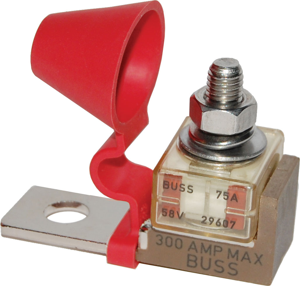
1) Would a bluesea terminal fuse be a good way to go for the fuses at the batteries?
2) the in-line fuse on our VHF radio is actually really close to the start of the wire, not at the radio. This means it would be OK to use to protect the entire line, correct?
 
Jan 11, 2014
12,320
Sabre 362 113 Fair Haven, NY
1) Would a bluesea terminal fuse be a good way to go for the fuses at the batteries?
Absolutely.

2) the in-line fuse on our VHF radio is actually really close to the start of the wire, not at the radio. This means it would be OK to use to protect the entire line, correct?
How close is close?
 
Jan 11, 2014
12,320
Sabre 362 113 Fair Haven, NY
Two answers.

It should be closer.

So long as there is nothing that might chafe the wires or cause them to short before the fuse, it is probably OK. Make sure the wires are secured and not flopping around and there are no sharp edges or anything else that could damage the wires in that short distance.
 
  • Like
Likes: Beth G

Beth G

.
Jun 2, 2023
15
Capital Yachts Neptune 24 Lake Ontario
Two answers.

It should be closer.

So long as there is nothing that might chafe the wires or cause them to short before the fuse, it is probably OK. Make sure the wires are secured and not flopping around and there are no sharp edges or anything else that could damage the wires in that short distance.
Yep, its going to be safely strung. Honestly it's probably even closer than 8". I haven't been to the boat in over a week, buy I do remember that it's quite close to where the battery is (his dad had it hooked direct to the house battery, I'm putting it after the 1/2/B switch and fuse so if the house battery is dead we can use the cranking battery to power the VHF).

Thanks again for all your assistance, I appreciate it and look forward to telling my husband he's safe to sail!
 
Oct 29, 2012
351
Catalina 30 TRBS MkII Milwaukee
Hi there! New boat owner here...we inherited our sailboat, and are redoing the wiring. I have made a wiring diagram, it's at the bottom of this, and am hoping to get some input on it. To help, here's a basic description of my systems:

1) The "positive" side of the DC system, going from batteries to the components:
  • a deep cycle house battery and a cranking battery for the outboard motor, utilizing a 1/2/both switch.
  • VHF radio, marine stereo, and switch panel connect to the 1/2/both switch (with a 50 Amp fuse before them, in line fuses for the radio and stereo, and my switch panel has integrated circuit breakers - yay no fuse box!)
  • Bilge system connects straight to the house battery, so it will run in automatic mode even if the 1/2/both switch is set to off. See, I'm learning!
2) For the negative (ground) side of the DC:
  • The house battery negatives are connected together.
  • I have the radio, stereo, and switch panel negatives combining in a negative "switch bus".
  • I belive the "common ground" I've created, hopefully without a ground loop is, the "ground bus" - the engine, batteries (via one of their negative terminals), bilge pump, and switch bus all connect to that bus.
3) AC system is very basic, and I've not drawn it other than the takeoff from its ground point: I have a shore power hookup that supplies 2 110V outlets, one of which has my battery charger plugged into it. The ground from this system will be connected to the DC ground to maintain one common ground.

My questions:
1) did I screw anything up?
2) I'm assuming that, since my breaker for everything being powered by the 1/2/off switch is 50A I need a cable gauge to safely carry that voltage from the switch bus to the DC ground bus?
3) is 50A massively big for the switch panel, VHF, stereo circuit? We could have bought a 30, but weren't sure and didn't want to undersize it.
4) what size ground wire would you use to hook the batteries up to the DC ground bus, and the DC ground bus to the engine? We are using 6 gauge positive cables to connect the batteries to the 1/2/off switch, it's less that 2' away from one of the batteries and 1' from the other one.
5) my husband feels we should connect the negative bilge pump wire direct to the battery instead of to the DC bus. Or, put the switch bus directly on the batteries as well, and connect the battery and AC ground straight to the engine, thus eliminating the ground bus. I'm not sure why, but that's making me leery. What are your thoughts?
View attachment 216408
No.... Do Not Bond the AC and DC systems together!
 

dLj

.
Mar 23, 2017
3,868
Belliure 41 Back in the Chesapeake
I appreciate it and look forward to telling my husband he's safe to sail!
@Beth G I was kinda hoping that would have been: "I appreciate it and look forward to telling my husband WE'RE safe to sail!" ....

Just yesterday I watched a solo woman sailor back her Hinckley into a slip making it look like it was easy.... (it's not)....

dj
 
Oct 26, 2008
6,216
Catalina 320 Barnegat, NJ
Beth, you put together an excellent diagram. With Dave's comments and the reading that John recommended you will be on your way to having a first class understanding about how electrics is done on a boat. I have a few questions & comments:
  • "Charges, Gauge" - I assume these are volt meters on your panel? They provide you with battery voltages for both the house and start battery? With added expense and installation complexity, you might consider a battery monitor for better understanding of the battery's condition.
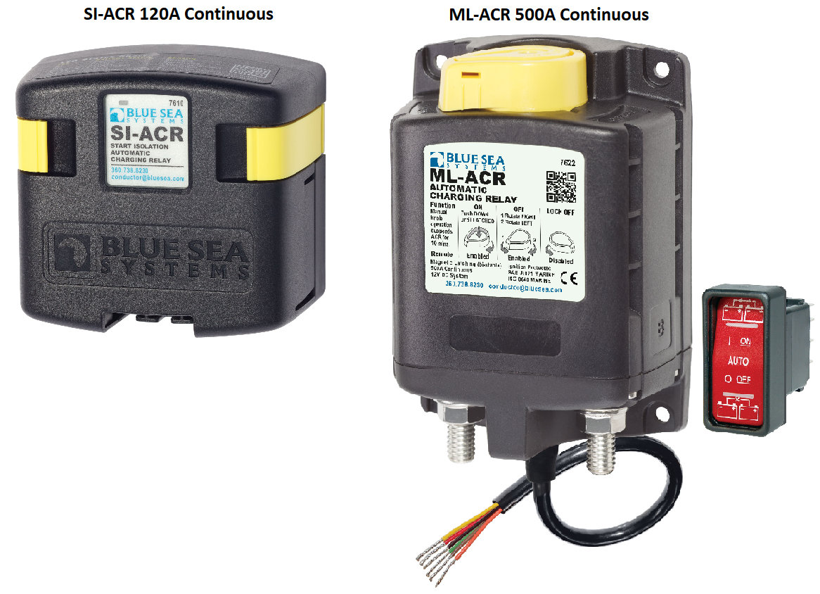
  • I might be missing something, but I don't see where your battery charger is introduced into the diagram. Typically, the charger is linked directly to the house bank (battery) - often via a positive buss that connects all charging sources (including alternator source). I understand your system is much simpler with an outboard. The charging current is then fed to the start battery via automatic charging relay (ACR) or echo charger, or simply by alternating the 1/2/B switch position appropriately.
  • BTW, how do you use the 1/2/B switch? I won't assume that you don't know how to operate the switch, but if you aren't aware, the switch requires some knowledge about how it works. If you aren't operating the switch in the appropriate manner, you may not be loading or charging your batteries properly or you may be combining both batteries improperly. It would be helpful if you describe your typical routine as it relates to the switch.
 
  • Helpful
Likes: jssailem
Oct 26, 2008
6,216
Catalina 320 Barnegat, NJ
The AC ground and DC negative should be tied together at a single point. The AC neutral should not be tied to AC ground or DC negative anywhere on the boat (assuming no inverter or generator is involved).
Yes, I see nothing wrong with the AC ground (in green) on the diagram linked to the DC Neg Buss.
 
Jan 11, 2014
12,320
Sabre 362 113 Fair Haven, NY
The AC ground and DC negative should be tied together at a single point. The AC neutral should not be tied to AC ground or DC negative anywhere on the boat (assuming no inverter or generator is involved).
Because the OPs boat is a small boat with an outboard, it presents an unusual situation for tying the AC ground to the DC- bus bar. It is complicated by the OB being an electric start. Connecting the AC ground to the DC- will make the OB's aluminum lower unit a sacrificial anode, unless a galvanic isolator is installed, a magnesium anode is connected to the system, and the OB is never in the water when plugged into shore power.

The battery charger is a plug in device, not a hard wired device. It is likely the case is grounded through the ground wire in the cord and to the shore power ground. I would be surprised if there are any other AC devices frequently used on board, such as an AC, refrigeration, Inverter, hot water tank, etc.

What we don't know is how the AC is wired on board, does it have a GFCI? Are both the Hot and Neutral protected by a circuit breaker? Are the ground and neutral connected any where? That is did some prior owner do a competent job installing the AC system?

In this case, if the only AC use is for the charger and small devices that are grounded through the ground wire or have isolated cases, I don't think it is necessary to connect the AC ground and the DC-, assuming (and it might be a big assumption) the anonymous prior owner did a reasonably competent job installing the AC system.
 

Beth G

.
Jun 2, 2023
15
Capital Yachts Neptune 24 Lake Ontario
Everything dlochner stated is correct. The charger has a 3-prong plug that goes into a 110V outlet on the boat, which is part of rhe AC system that is ONLY energized via plugging the boat into shore power, with the grounding from rhe boat's ac system connecting to the ground on the shore power hookup. I should not need this system to be grounded to the engine, as it won't be energized unless I'm connected to the shore power system at my dock. And yes, my AC system has a GFCI'd outlet, fuse, and I'm looking into adding ELCI protection on the boat.

We are brand new to sailing, and I don't forsee taking a long trip that would require AC power, or a generator/solar array to charge my batteries, for a very long time.

Because the OPs boat is a small boat with an outboard, it presents an unusual situation for tying the AC ground to the DC- bus bar. It is complicated by the OB being an electric start. Connecting the AC ground to the DC- will make the OB's aluminum lower unit a sacrificial anode, unless a galvanic isolator is installed, a magnesium anode is connected to the system, and the OB is never in the water when plugged into shore power.

The battery charger is a plug in device, not a hard wired device. It is likely the case is grounded through the ground wire in the cord and to the shore power ground. I would be surprised if there are any other AC devices frequently used on board, such as an AC, refrigeration, Inverter, hot water tank, etc.

What we don't know is how the AC is wired on board, does it have a GFCI? Are both the Hot and Neutral protected by a circuit breaker? Are the ground and neutral connected any where? That is did some prior owner do a competent job installing the AC system?

In this case, if the only AC use is for the charger and small devices that are grounded through the ground wire or have isolated cases, I don't think it is necessary to connect the AC ground and the DC-, assuming (and it might be a big assumption) the anonymous prior owner did a reasonably competent job installing the AC system.