Building a DC Electrical Foundation

Feb 6, 1998
11,722
Canadian Sailcraft 36T Casco Bay, ME
Did you include an AC diagram? I'm particularly interested in the AC ground to DC ground connection.
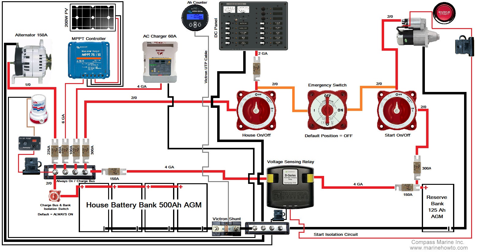
No, as stated, this is only the DC Foundation diagram.

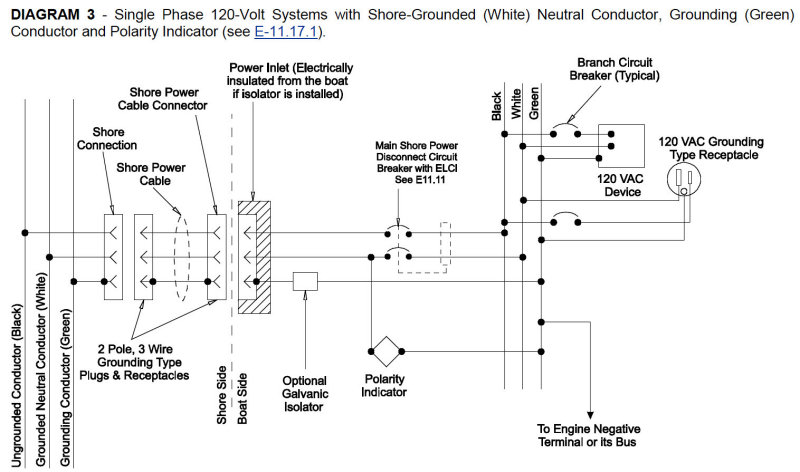
AC Green/Protective Earth is always connected to the vessels DC ground.

It is critically important that AC White/Neutral never be bonded to AC Green except back on shore. There are a few exceptions to the Neutral to Grounding bond though. If you have an inverter or generator then this bond needs to occur only when those devices are operating and this neutral to ground bond can only be made while physically inverting for AC or physically generating AC power.

This is what a typical basic AC install would look like: (Note the green grounding wire goes to DC engine negative terminal or its bus)
 
  • Like
Likes: MFD

jssailem

SBO Weather and Forecasting Forum Jim & John
Oct 22, 2014
23,579
CAL 35 Cruiser #21 moored EVERETT WA
Thank you MaineSail.
 
Oct 26, 2008
6,334
Catalina 320 Barnegat, NJ
Thanks for that! I have not used AC power on my boat yet. However, I am in the process of installing an AC powered water heater and AC batt charger, so my concern for the AC side has been magnified. Years ago, I disconnected the safety ground conductor that I found clamped to the neg battery post, fearing that it had not been done properly. I resolved at that time not to even connect to shore power until I was able to verify the entire system is done right.
 
Oct 26, 2008
6,334
Catalina 320 Barnegat, NJ
Another question .... I'm confused about the lack of information about power receptacles and receptacle boxes for use with the boats interior. The only components that I find are extremely expensive, for instance a Marinco receptacle for $40 (not even GFCI) and boxes that are even more costly. Are the yellow receptacles and boxes an indication that it is suitable for exterior installation? Can you go to HD and get normal house receptacles and boxes for use inside the cabin (like the ones I find installed in my boat)?
 
Feb 9, 2015
11
Ericson E-34 Lk Champlain
What is the red device between the starter and the fuse in the start isolation circuit, and shouldn't the fuse be in between the starter and the device?
 
Feb 6, 1998
11,722
Canadian Sailcraft 36T Casco Bay, ME
Another question .... I'm confused about the lack of information about power receptacles and receptacle boxes for use with the boats interior. The only components that I find are extremely expensive, for instance a Marinco receptacle for $40 (not even GFCI) and boxes that are even more costly. Are the yellow receptacles and boxes an indication that it is suitable for exterior installation? Can you go to HD and get normal house receptacles and boxes for use inside the cabin (like the ones I find installed in my boat)?

I use plastic outlet and j-boxes and replace the steel screws with SS. As for outlets etc. I use hospital grade with tinned internals. They cost a bit more but hold up better. Bare brass does not do well in a marine application. Same for GFCI's.. The stuff from a marine store, in a Marinco package, is usually repackaged low to mid grade Leviton such as a 7599-W Leviton GFCI that costs about $40.00 in a marine package and about $10.00 from an electrical supply house...
 
Oct 26, 2008
6,334
Catalina 320 Barnegat, NJ
Great tip. I'll upgrade all my outlets while I'm at it. I plan on changing out the wiring as well. Thanks!
 

RolfP

.
Feb 16, 2015
7
Morgan 383 Port Superior WI
Any chance I can get some opinions on my ASIS and TOBE diagrams? I diagramed the current state of the battery connections (after three owners, including me, doing what they do), and a concept of how I might use what I have plus add some things in order to at least get safe, and get closer to keep track of the state of my house bank.
 

Attachments

Jul 27, 2020
14
Hunter 34 Kingston
Any chance I can get some opinions on my ASIS and TOBE diagrams? I diagramed the current state of the battery connections (after three owners, including me, doing what they do), and a concept of how I might use what I have plus add some things in order to at least get safe, and get closer to keep track of the state of my house bank.
Hi RolfP
did you ever figure out where the pos from the ACR connects.
 

Tim22

.
Jun 16, 2014
255
Hunter 310 Ottawa
Curious to know how the foundation would work if the house bank we’re LiFePO4. I’m particularly interested if this would cause problems with the emergency switch configuration?

Tim
 
Feb 6, 1998
11,722
Canadian Sailcraft 36T Casco Bay, ME
Curious to know how the foundation would work if the house bank we’re LiFePO4. I’m particularly interested if this would cause problems with the emergency switch configuration?

Tim
This particular diagram was not drawn for LiFePO4 systems. A lot of folks are hacking together or "dropping-in" LFP batteries and the systems are typically not well designed nor even safe in many cases. There is a lot more to LFP installations than just "drop-in" as many markets are suggesting..

This smoked alternator stator happened just a few weeks ago with a stock Hitachi alternator..

"But, the manufacturer said they were drop-in replacements?"
 
Jun 21, 2020
2
Catalina 36 Long Beach
Maine Sail,
In the diagram you created for your client (post #1, above) I noted a fuse leading from the House on/off to the DC panel. The amperage of this fuse was not stated. I also noted a 300A fuse leading from the left-most stud of the positive charge bus to the House on/off switch, presumably to protect the 2/0 gauge wire leading to the house switch. My question is this: Should the unlabeled fuse from the switch to panel be rated far lower than 300A? I'm assuming that unlabeled fuse is to protect the panel itself and this panel (if I'm not mistaken) has a max amp rating of 50A, so the fuse should be 50A or less. Does this sound correct?
Another question is this: Can I duplicate this setup on my C36 whilst still retaining the old FLA batteries (that will eventually be swapped out with AGMs) and the old 51A alternator (which will eventually be replaced with something with higher output and will also include the external regulator you described in your post)? I mainly want to know if this setup (sans new alternator and regulator) will hasten the demise of my already crappy FLA batteries.
Thank you for the great wisdom and help you've provided to all us newbies through your posts and awesome MarineHowTo website!
 
Oct 18, 2025
1
Broadened Horizons Custom 55 Ft Aluminum Catamaran Fort Myers
When I am asked to make a drawing of the installed system I will ask the owner if they want an electrical layout drawn using standardized electrical symbols or an electrical layout using images of the actual installed products. Most boat owners, unless they are electrical engineers, simply don't understand electrical schematics or know what the symbols mean so they usually opt for a drawling like this one. There is no sense handing someone a drawing for their boats system if the language it's drawn up in is foreign to them.


Maine Sail, I love your beautiful drawing! I want to create one like it to document the 48 Volt DC system I designed for my boat. Can I ask what software tool you used? Something simple like Google Drawing or a specific diagramming tool? I've looked at a few different ones but none of them keep it nice and simple like you did here. if there was a tool with all of the images of the components in it would be even better or did you create your own clip art small little images in a folder you'd be willing to share?