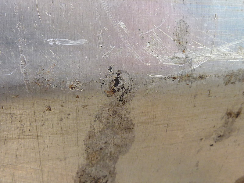
This tank bottom is vee-shaped thus any debris or crud winds up in the vee. The tank bed was very well designed and the vee is suspended in air on all sides so no moisture was in contact with the tank but still after 31 years of service she began leaking.
When we cut the tank open I sifted thought the dead organisms and found a chunk of dissimilar metal directly over the pin hole. It seemed to possibly be a piece of stainless steel that had somehow fallen into the tank somewhere along the way, possibly during a sending unit change out or even during the manufacturing process?
I suspect that this piece of errant metal was the cause of the pin hole. There were no other signs of corrosion despite this being a 31 year old aluminum tank. Canadian Sailcraft (CS Yachts) did a very good job designing & engineering the fuel tank & beds. In reality I probably could have re-used the tank but decided not to repair it.
The first step in replacing any fuel tank is to remove all the old fuel. Seeing as I was planning on adding a dedicated fuel polishing system I used the new fuel polishing system pump I chose. I made a home made stand out of some plywood and mounted the pump to it. I then connected some fuel hose a shut off valve, a 12v pigtail and a switch. I simply transferred the fuel in 5 gallon cans, through the Racor filter and I burned it in my homes oil boiler. I drain my tank every winter anyway but usually use the small Purolator/Facet pump on the engine, but this pumps is slow. The Carter GP4389 pump filled the tanks in short order.
The Pin Hole:
Like anything in life nothing lasts forever, including impossible to access fuel tanks. This tank was on a CS-36T and ran port to starboard under the cockpit sole behind the engine.
At first I rather delusionally thought the tank may come out through the port lazarette, but I was sorely mistaken. After carefully measuring and re-measuring it was clear that this was not going to happen.
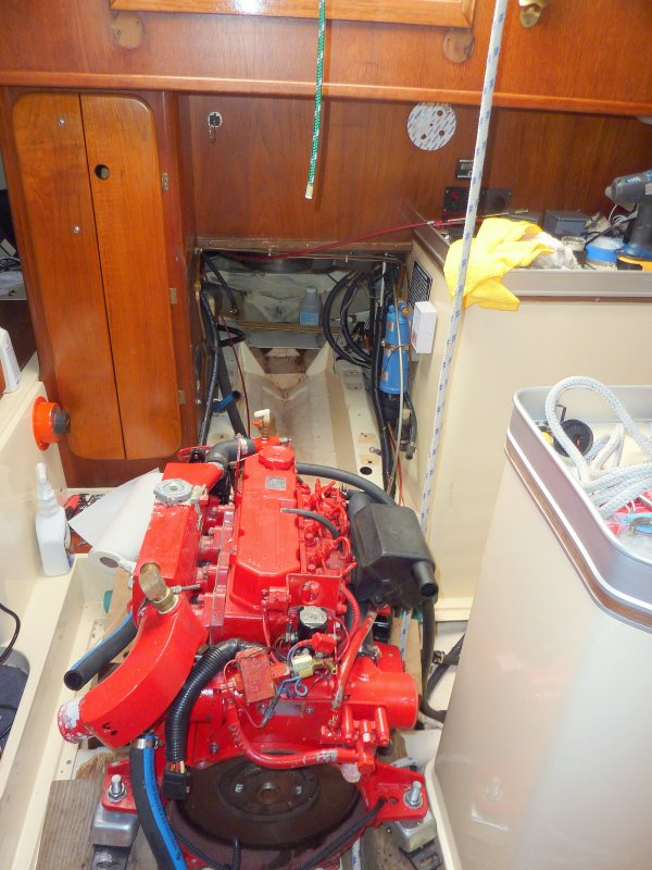
This photo shows the first big step in this project, removing the engine. For removal I enlisted my main sheet, an old boom vang and a 4X4 across the companionway. Once everything was disconnected and the gear box removed, the engine came out quite easily. I had Tim R. there just in case but this could easily be done solo on this particular boat and many others like her.
Coming Out:

To move the engine into the galley I had first removed the cabin sole to prevent damaging it. I then covered the gelcoat parts of the interior with some heavy vinyl and collected some boat yard blocks and gently set the engine down on them. She sat there while the new tank was fabricated and gave me good access to remove, refinish and replace some engine parts that are just tough tog et at otherwise.
In this photo the fuel tank has already been removed & the engine is sitting in the galley.
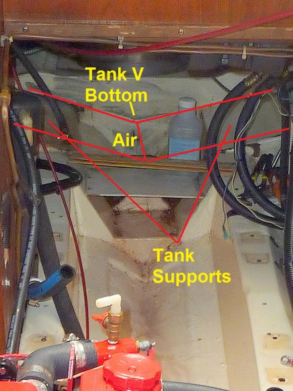
Using MS Paint I have illustrated, rather crudely, where the vee in the tank was. As you can see it was not in contact with anything and it's highly unlikely that the pin hole started from the outside, as usually happens. There was no corrosion under the tank support beds which are gelcoated fiberglass. The pin hole was right at the bottom of the vee in the tank.
The tank location:
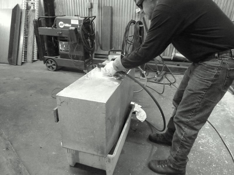
Records and discussion with the PO indicated that this tank had been running biocides since new and Soltron or Startron for the last 15+ years. Because of this I wanted to see how well it kept my tank clean but at 31 years old, I was doubtful. Not one to believe in snake oils I chose to cut the old tank open and see for myself.
DO NOT try this at home without the skills or knowledge or you could go boom:
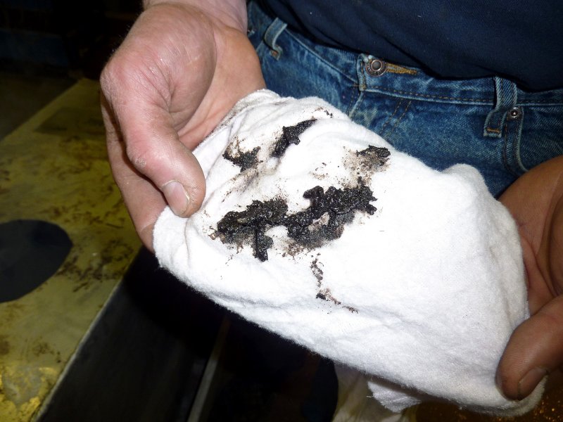
With a hole cut we simply took a clean rag and blindly wiped an inner wall of the tank. Not clean. If you thing fuel treatments will clean your tank think again. The only thing that will effectively clean a dirty tank is a good physical cleaning through clean out ports.
This view is looking down into the hole cut in the tank you can see the piece of metal that fell into the tank, a baffle and also a LOT of tank grunge and grime. Remember, this boat used Soltron well before it was marketed in the US as Startron, and it had been in use religiously for the last 15+ years, yet this is what the interior looked like. I do think Startron does have some benefits but keeping a tank clean or actually cleaning it are not features of this product that can be relied upon.
Nasty!!

Here's a view looking off towards the sending unit. No wonder the gauge was not very accurate.
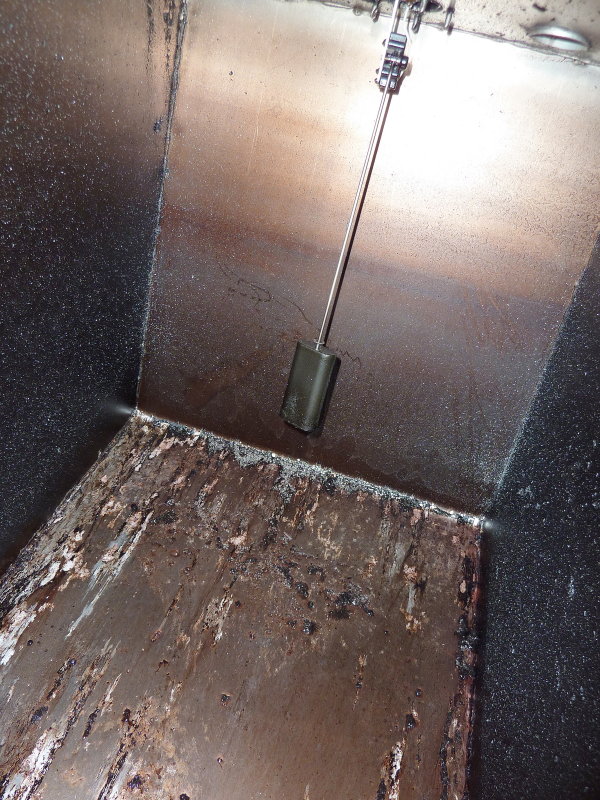
Having never been a huge believer in the drastic tank condensation theories that are bantered around, I wanted to see for myself how much water was actually in the absolute bottom of my tank. The answer was nada, zilch & nothing. Those gray flakes are from the plasma cutter and the fuel looked bad, but still no water separated out at all. I found it rather interesting that after 31 years I found absolutely no water in this fuel tank. Perhaps the fuel treatments really do work for something..? The previous owner never even topped it off in the winter, and I drain it, but still the original pick up tube was 1.4" off the dead bottom of the tank so you never get it all. I will continue to change the deck fill o-rings yearly as it does seem to work well.

As an ABYC member I tried to build my tank to the letter of the standard. This meant no mixing of copper alloys with the aluminum tank as many manufacturers did and still do.
So, where the heck do I find aluminum tank fittings? I asked a friend at Morris Yachts where they got their fittings and he sent me to Luther's Welding in Bristol, RI 401-253-5550. Sure enough they had aluminum tank fittings, and shipped out exactly what I ordered, and for a very reasonable price to boot. Great folks to deal with and beautiful fittings.
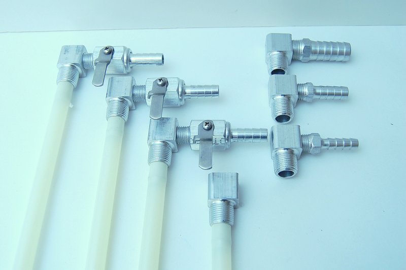
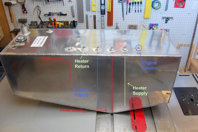
I designed the new tank with multiple tappings and two baffles as opposed to just one. There is a supply/return for the engine, supply/return for a diesel fired cabin heater and a supply/return for a dedicated fuel polishing system. I did not install tank clean out ports because access to the top of the tank is extremely limited and clean outs would have been just one more potential leak point. I suppose I could eventually remove it and install clean out ports but that is likely 10-15 years out, if at all, with this polishing system. I have a friend with a very high quality scope camera that we can inspect the tank cleanliness with in the mean time to assess any need for physical cleaning. These cameras are great for inspecting empty fuel tanks.
When designing the tank for a fuel polishing system I definitely wanted to get my polishing pick up directly over the deepest part of the tank in order scrub/polish every last little bit of the fuel. This pick up tube is 1/8" off the dead bottom of the tank and directly over the V where any crud/dead fuel bugs/algae or other junk should naturally wind up.
In order to avoid foaming with a high flow polishing system the return for the polishing system is also returned via a dip tube. Returning the fuel below the level of the fuel prevents and or greatly minimizes the potential for fuel foaming.
During the design process I spoke with many experts on fuel filtration including our own Rich H., Parker/Racor, SeaBoard Marine and others. There are LOTS of options out there and this can be done any number of ways but I wanted it simple yet effective. After talking with many fule filtration experts I decided I wanted a dedicated high flow/turnover system of at least twice per hour when polishing. I also decided I wanted the system to run when the engine ran and when the engine was not running if needed. I felt it was important to let it run with the tank fuel sloshing about when under power or motor sailing in order to catch any crud stirred up.
This photo shows a drawing of the pickup or dip tubes and the supply/return tapping locations.
When installing tank fittings it is critically important that you don't get any teflon tape or pipe dope residue into the tank. If you look close you'll see that I have wiped on the thread sealant and then cleaned the first two threads with a rag. Doing this prevents getting pipe dope into the fuel tank.
Teflon tape is not recommended in fuel systems. I suspect this advisory from Racor and others is more for the common denominator factor than anything else. I suspect it could very well be used, if applied correctly, but I still don't use it in fuel systems, just dope.
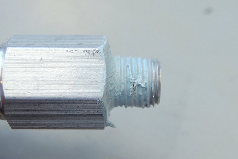
My preferred thread sealant for diesel or #2 oil is Hercules Megaloc. It is diesel rated and works very, very well and also cleans up easily. It never fully hardens which makes slight fitting adjustments in the future doable without loosing the thread sealing properties. Hercules Megaloc is available at most any good plumbing supply house but there are many diesel/#2 rated thread sealants on the market t choose from. The key is to use them correctly and not be sloppy.
Megaloc Info:
"MEGALOC is applied easily with a natural bristle brush even at
temperatures as low as -25°F, and performs over a temperature range
of -50°F to +400°F. It provides leak-proof hydraulic resistance to 12,000
psi and withstands gas pressure up to 2,600 psi. MEGALOC is
non-toxic, non-hazardous, and non-flammable. It contains no lead,
heavy metals, or volatile solvents."
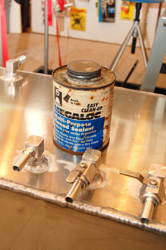
With luck, any aluminum tank you buy will have been properly pressure tested at the manufacture before delivery. Aluminum is soft and thus the plugs used for pressure testing tend to be harder than the aluminum and can bugger up the threads slightly.
For safety's sake I always chase aluminum threads before installing fittings into an aluminum tank. You will need an NPT tap to match the tank tapping threads for this task. Don't go crazy all you want to do is make sure they are smooth and free of debris or shavings. These tappings were all 3/8 X 18 NPT. After you chase and clean the tappings you'll then want to vacuum out the inside of the tank as best you can. I used a piece of PEX tube on my shop vac for this.

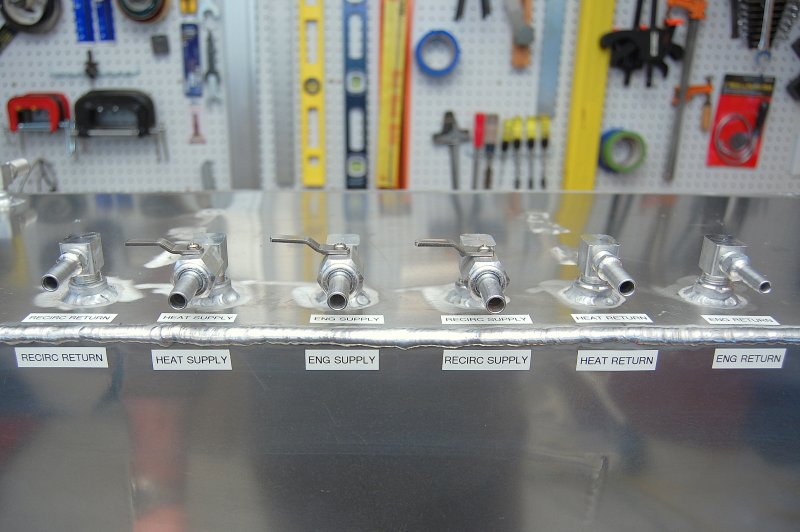
In this picture all the aluminum tank fittings have been installed and any pipe dope residue wiped clean.

For future reference, or a future owner, I labeled the tappings on both the face of the tank and the top with a label maker. I also had wrote with a fine point Sharpie marker under the labels just in case.
On the CS-36T the tank runs port to starboard behind the engine and under the cockpit. Because of this the engine clearly has to be removed to replace the tank. Removing the gear box and using a block and tackle, AKA main sheet, in the companionway made this an easy task. As discussed earlier I simply set the engine in the galley while waiting for the new tank.
This photo shows the new tank ready to go and set into place for the navigation into the engine bay. Even with the engine out this was still a tight fit.
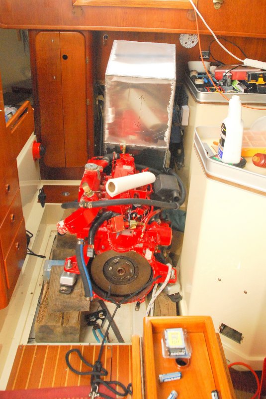
View from inside the engine compartment during the install process.
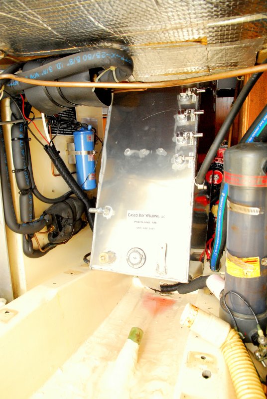
The tank just barely fit between the engine bed stringers, which is exactly what needed to be done in order to get it in & out.
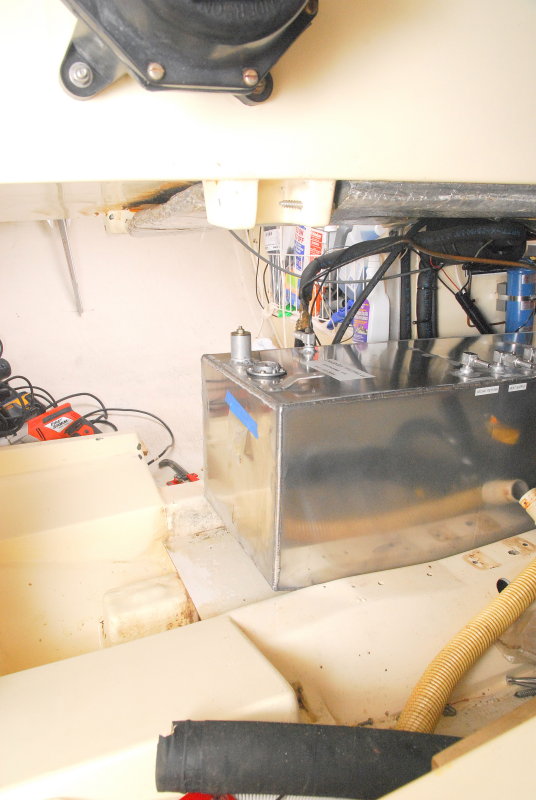
Once the tank was in the engine compartment it then needed to be rotated in a port/starboard orientation. I also took the liberty of replacing the hot water heater when the tank was out. I did this under the old "while your in there" DIY clause.
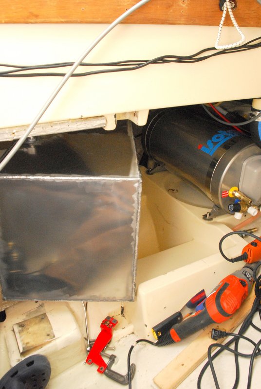
Once fitted into place I began to re-install the tank supports, hoses and associated hardware.

In order to facilitate my polishing system design I needed to make a mounting board to fit across the fore edge of the tank that was bolted to the aluminum tank support brackets. This board holds the polishing pump, Racor 900 polishing filter and the primary engine fuel filter, a Racor 500.

Here is a good basic view of the entire polishing and primary engine filtration system with the engine re-installed.. The only thing missing from this photo is the vacuum gauge for the polishing filter.
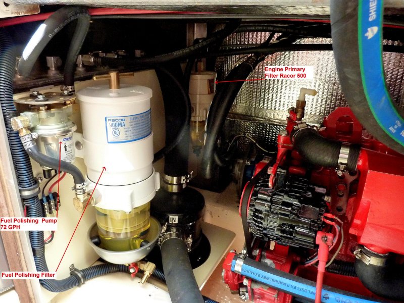
I chose the Racor 900MA filter for my polishing filter housing. I also installed a drag needle vacuum gauge to monitor filter performance so I am not changing it prematurely. The system is designed to run whenever the engine is running and turns the entire contents of the tank roughly twice per hour. I also installed a switch so it can run independently of the engine, or not run it when the engine is on.
There are plenty of less expensive filters you could use that will work equally as well so don't feel you need to spend big bucks on a Racor. For me I prefer the Racor, as I know them in-side and out, and I know Hamilton marine has a massive stock of any part I would ever need for it. Compared to some other filters the cartridge has less sq. in of surface area but for this system it is very well sized and suited.
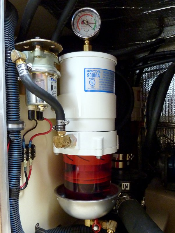
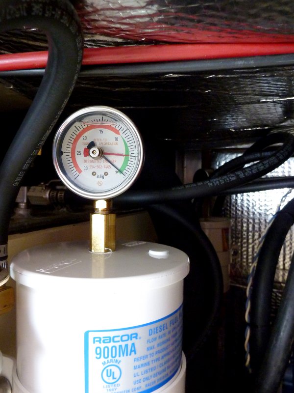
The red needle is moved or dragged by the black vacuum needle and I pinched off the valve slightly to show how it works. Once moved due to vacuum it simply stays where the highest vacuum was generated until you manually re-set it. Because this fuel pump is only running a polishing loop from the tank, through the filter then back into the tank, I can see very easily see when the filter begins to plug. A nice feature of a drag needle gauge is that I do not need the system running to view how clogged or restricted the filter is becoming.
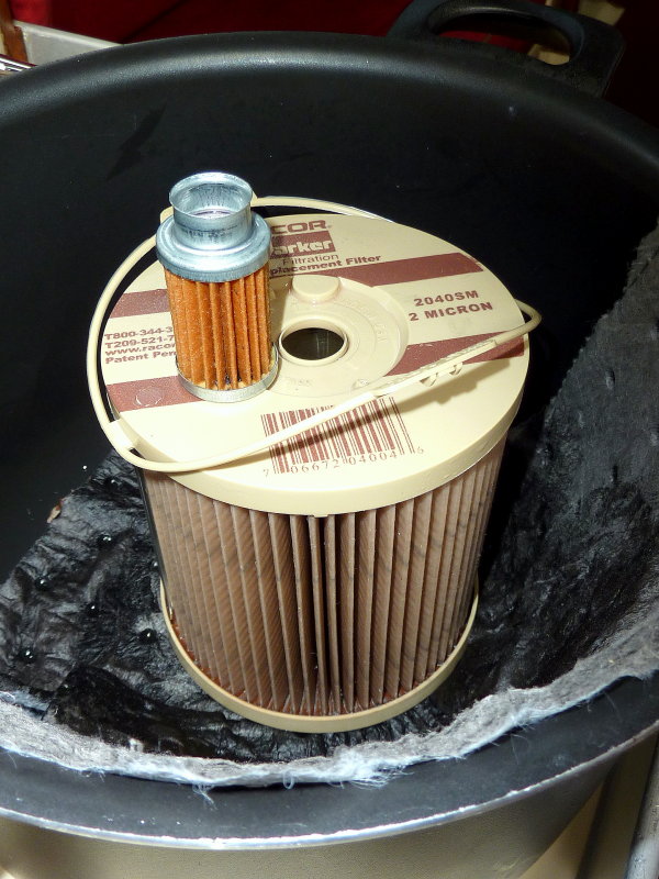
This season I ran the fuel polishing system for roughly 190 hours and the engine for 111 hours. The filter on top is the Westerbeke secondary on-engine filter. Both were installed at the same time. The on-engine filter is like new and at this rate could probably go five or more seasons before changing but I don't like to let the filter paper sit in fuel for that long so I'll change it bi-yearly as opposed to yearly.
I originally designed the polishing system for a 10 micron filter but the 900MA came with a 2 micron element so rather than waste it I used it. This element still looks almost brand new and had no additional vacuum after approx 190 hours of polishing, which I was surprised by. If you do the math that is roughly 13,300 gallons filtered using @ 70 GPH flow rate. It has done an amazing job of keeping my primary Racor clean and my secondary on-engine filter literally spotless. I see no reason to not continue using a 2 micron element in my polishing system. Perhaps because I started with a barnd new tank the 2 mic filter is a good match? I am running a 10 micron in my primary Racor 500 and that one also looked just as new at 111 hours of engine run time.
It is clear that if you install a well designed polishing system, from the beginning, with a pick up tube at the dead bottom of the tank, that the tank can remain very, very clean for a long time to come and your other filters will have little work to do..
In the last 5 years with this motor I have never once seen the Racor elements come out of my primary filter looking anywhere near as clean as they did at the end of this year. Usually they are black in color. This is a real testament to the efficacy of this polishing system.
In summary I am running a 2 micron element in the Racor 900 polishing filter, though probably not necessary, and a 10 micron element in my primary Racor 500 for the engine. All is purring along like a kitten and everything is clean.
There are many pump and filter manufacturers to choose from here are a few:
Seaboard Marine Inc. (LINK)
Shelco FO Series Filters (LINK)
Walbro Fuel Pumps (LINK)
When we cut the tank open I sifted thought the dead organisms and found a chunk of dissimilar metal directly over the pin hole. It seemed to possibly be a piece of stainless steel that had somehow fallen into the tank somewhere along the way, possibly during a sending unit change out or even during the manufacturing process?
I suspect that this piece of errant metal was the cause of the pin hole. There were no other signs of corrosion despite this being a 31 year old aluminum tank. Canadian Sailcraft (CS Yachts) did a very good job designing & engineering the fuel tank & beds. In reality I probably could have re-used the tank but decided not to repair it.
The first step in replacing any fuel tank is to remove all the old fuel. Seeing as I was planning on adding a dedicated fuel polishing system I used the new fuel polishing system pump I chose. I made a home made stand out of some plywood and mounted the pump to it. I then connected some fuel hose a shut off valve, a 12v pigtail and a switch. I simply transferred the fuel in 5 gallon cans, through the Racor filter and I burned it in my homes oil boiler. I drain my tank every winter anyway but usually use the small Purolator/Facet pump on the engine, but this pumps is slow. The Carter GP4389 pump filled the tanks in short order.
The Pin Hole:

Like anything in life nothing lasts forever, including impossible to access fuel tanks. This tank was on a CS-36T and ran port to starboard under the cockpit sole behind the engine.
At first I rather delusionally thought the tank may come out through the port lazarette, but I was sorely mistaken. After carefully measuring and re-measuring it was clear that this was not going to happen.
This photo shows the first big step in this project, removing the engine. For removal I enlisted my main sheet, an old boom vang and a 4X4 across the companionway. Once everything was disconnected and the gear box removed, the engine came out quite easily. I had Tim R. there just in case but this could easily be done solo on this particular boat and many others like her.
Coming Out:

To move the engine into the galley I had first removed the cabin sole to prevent damaging it. I then covered the gelcoat parts of the interior with some heavy vinyl and collected some boat yard blocks and gently set the engine down on them. She sat there while the new tank was fabricated and gave me good access to remove, refinish and replace some engine parts that are just tough tog et at otherwise.
In this photo the fuel tank has already been removed & the engine is sitting in the galley.

Using MS Paint I have illustrated, rather crudely, where the vee in the tank was. As you can see it was not in contact with anything and it's highly unlikely that the pin hole started from the outside, as usually happens. There was no corrosion under the tank support beds which are gelcoated fiberglass. The pin hole was right at the bottom of the vee in the tank.
The tank location:

Records and discussion with the PO indicated that this tank had been running biocides since new and Soltron or Startron for the last 15+ years. Because of this I wanted to see how well it kept my tank clean but at 31 years old, I was doubtful. Not one to believe in snake oils I chose to cut the old tank open and see for myself.
DO NOT try this at home without the skills or knowledge or you could go boom:

With a hole cut we simply took a clean rag and blindly wiped an inner wall of the tank. Not clean. If you thing fuel treatments will clean your tank think again. The only thing that will effectively clean a dirty tank is a good physical cleaning through clean out ports.

This view is looking down into the hole cut in the tank you can see the piece of metal that fell into the tank, a baffle and also a LOT of tank grunge and grime. Remember, this boat used Soltron well before it was marketed in the US as Startron, and it had been in use religiously for the last 15+ years, yet this is what the interior looked like. I do think Startron does have some benefits but keeping a tank clean or actually cleaning it are not features of this product that can be relied upon.
Nasty!!

Here's a view looking off towards the sending unit. No wonder the gauge was not very accurate.

Having never been a huge believer in the drastic tank condensation theories that are bantered around, I wanted to see for myself how much water was actually in the absolute bottom of my tank. The answer was nada, zilch & nothing. Those gray flakes are from the plasma cutter and the fuel looked bad, but still no water separated out at all. I found it rather interesting that after 31 years I found absolutely no water in this fuel tank. Perhaps the fuel treatments really do work for something..? The previous owner never even topped it off in the winter, and I drain it, but still the original pick up tube was 1.4" off the dead bottom of the tank so you never get it all. I will continue to change the deck fill o-rings yearly as it does seem to work well.

As an ABYC member I tried to build my tank to the letter of the standard. This meant no mixing of copper alloys with the aluminum tank as many manufacturers did and still do.
So, where the heck do I find aluminum tank fittings? I asked a friend at Morris Yachts where they got their fittings and he sent me to Luther's Welding in Bristol, RI 401-253-5550. Sure enough they had aluminum tank fittings, and shipped out exactly what I ordered, and for a very reasonable price to boot. Great folks to deal with and beautiful fittings.

I designed the new tank with multiple tappings and two baffles as opposed to just one. There is a supply/return for the engine, supply/return for a diesel fired cabin heater and a supply/return for a dedicated fuel polishing system. I did not install tank clean out ports because access to the top of the tank is extremely limited and clean outs would have been just one more potential leak point. I suppose I could eventually remove it and install clean out ports but that is likely 10-15 years out, if at all, with this polishing system. I have a friend with a very high quality scope camera that we can inspect the tank cleanliness with in the mean time to assess any need for physical cleaning. These cameras are great for inspecting empty fuel tanks.
When designing the tank for a fuel polishing system I definitely wanted to get my polishing pick up directly over the deepest part of the tank in order scrub/polish every last little bit of the fuel. This pick up tube is 1/8" off the dead bottom of the tank and directly over the V where any crud/dead fuel bugs/algae or other junk should naturally wind up.
In order to avoid foaming with a high flow polishing system the return for the polishing system is also returned via a dip tube. Returning the fuel below the level of the fuel prevents and or greatly minimizes the potential for fuel foaming.
During the design process I spoke with many experts on fuel filtration including our own Rich H., Parker/Racor, SeaBoard Marine and others. There are LOTS of options out there and this can be done any number of ways but I wanted it simple yet effective. After talking with many fule filtration experts I decided I wanted a dedicated high flow/turnover system of at least twice per hour when polishing. I also decided I wanted the system to run when the engine ran and when the engine was not running if needed. I felt it was important to let it run with the tank fuel sloshing about when under power or motor sailing in order to catch any crud stirred up.
This photo shows a drawing of the pickup or dip tubes and the supply/return tapping locations.

When installing tank fittings it is critically important that you don't get any teflon tape or pipe dope residue into the tank. If you look close you'll see that I have wiped on the thread sealant and then cleaned the first two threads with a rag. Doing this prevents getting pipe dope into the fuel tank.
Teflon tape is not recommended in fuel systems. I suspect this advisory from Racor and others is more for the common denominator factor than anything else. I suspect it could very well be used, if applied correctly, but I still don't use it in fuel systems, just dope.

My preferred thread sealant for diesel or #2 oil is Hercules Megaloc. It is diesel rated and works very, very well and also cleans up easily. It never fully hardens which makes slight fitting adjustments in the future doable without loosing the thread sealing properties. Hercules Megaloc is available at most any good plumbing supply house but there are many diesel/#2 rated thread sealants on the market t choose from. The key is to use them correctly and not be sloppy.
Megaloc Info:
"MEGALOC is applied easily with a natural bristle brush even at
temperatures as low as -25°F, and performs over a temperature range
of -50°F to +400°F. It provides leak-proof hydraulic resistance to 12,000
psi and withstands gas pressure up to 2,600 psi. MEGALOC is
non-toxic, non-hazardous, and non-flammable. It contains no lead,
heavy metals, or volatile solvents."

With luck, any aluminum tank you buy will have been properly pressure tested at the manufacture before delivery. Aluminum is soft and thus the plugs used for pressure testing tend to be harder than the aluminum and can bugger up the threads slightly.
For safety's sake I always chase aluminum threads before installing fittings into an aluminum tank. You will need an NPT tap to match the tank tapping threads for this task. Don't go crazy all you want to do is make sure they are smooth and free of debris or shavings. These tappings were all 3/8 X 18 NPT. After you chase and clean the tappings you'll then want to vacuum out the inside of the tank as best you can. I used a piece of PEX tube on my shop vac for this.

In this picture all the aluminum tank fittings have been installed and any pipe dope residue wiped clean.

For future reference, or a future owner, I labeled the tappings on both the face of the tank and the top with a label maker. I also had wrote with a fine point Sharpie marker under the labels just in case.

On the CS-36T the tank runs port to starboard behind the engine and under the cockpit. Because of this the engine clearly has to be removed to replace the tank. Removing the gear box and using a block and tackle, AKA main sheet, in the companionway made this an easy task. As discussed earlier I simply set the engine in the galley while waiting for the new tank.
This photo shows the new tank ready to go and set into place for the navigation into the engine bay. Even with the engine out this was still a tight fit.

View from inside the engine compartment during the install process.

The tank just barely fit between the engine bed stringers, which is exactly what needed to be done in order to get it in & out.

Once the tank was in the engine compartment it then needed to be rotated in a port/starboard orientation. I also took the liberty of replacing the hot water heater when the tank was out. I did this under the old "while your in there" DIY clause.

Once fitted into place I began to re-install the tank supports, hoses and associated hardware.

In order to facilitate my polishing system design I needed to make a mounting board to fit across the fore edge of the tank that was bolted to the aluminum tank support brackets. This board holds the polishing pump, Racor 900 polishing filter and the primary engine fuel filter, a Racor 500.

Here is a good basic view of the entire polishing and primary engine filtration system with the engine re-installed.. The only thing missing from this photo is the vacuum gauge for the polishing filter.

I chose the Racor 900MA filter for my polishing filter housing. I also installed a drag needle vacuum gauge to monitor filter performance so I am not changing it prematurely. The system is designed to run whenever the engine is running and turns the entire contents of the tank roughly twice per hour. I also installed a switch so it can run independently of the engine, or not run it when the engine is on.
There are plenty of less expensive filters you could use that will work equally as well so don't feel you need to spend big bucks on a Racor. For me I prefer the Racor, as I know them in-side and out, and I know Hamilton marine has a massive stock of any part I would ever need for it. Compared to some other filters the cartridge has less sq. in of surface area but for this system it is very well sized and suited.

The red needle is moved or dragged by the black vacuum needle and I pinched off the valve slightly to show how it works. Once moved due to vacuum it simply stays where the highest vacuum was generated until you manually re-set it. Because this fuel pump is only running a polishing loop from the tank, through the filter then back into the tank, I can see very easily see when the filter begins to plug. A nice feature of a drag needle gauge is that I do not need the system running to view how clogged or restricted the filter is becoming.

This season I ran the fuel polishing system for roughly 190 hours and the engine for 111 hours. The filter on top is the Westerbeke secondary on-engine filter. Both were installed at the same time. The on-engine filter is like new and at this rate could probably go five or more seasons before changing but I don't like to let the filter paper sit in fuel for that long so I'll change it bi-yearly as opposed to yearly.
I originally designed the polishing system for a 10 micron filter but the 900MA came with a 2 micron element so rather than waste it I used it. This element still looks almost brand new and had no additional vacuum after approx 190 hours of polishing, which I was surprised by. If you do the math that is roughly 13,300 gallons filtered using @ 70 GPH flow rate. It has done an amazing job of keeping my primary Racor clean and my secondary on-engine filter literally spotless. I see no reason to not continue using a 2 micron element in my polishing system. Perhaps because I started with a barnd new tank the 2 mic filter is a good match? I am running a 10 micron in my primary Racor 500 and that one also looked just as new at 111 hours of engine run time.
It is clear that if you install a well designed polishing system, from the beginning, with a pick up tube at the dead bottom of the tank, that the tank can remain very, very clean for a long time to come and your other filters will have little work to do..
In the last 5 years with this motor I have never once seen the Racor elements come out of my primary filter looking anywhere near as clean as they did at the end of this year. Usually they are black in color. This is a real testament to the efficacy of this polishing system.
In summary I am running a 2 micron element in the Racor 900 polishing filter, though probably not necessary, and a 10 micron element in my primary Racor 500 for the engine. All is purring along like a kitten and everything is clean.

There are many pump and filter manufacturers to choose from here are a few:
Seaboard Marine Inc. (LINK)
Shelco FO Series Filters (LINK)
Walbro Fuel Pumps (LINK)

