Engine Charging Questions
- Thread starter Rick D
- Start date
Rick where does the alternator output go to? Is it connected directly to the house battery or to the isolator input stud. Can you draw us a diagram? Maybe snap a photo of the isolator?This just gets weirder. Today, I replaced the fuse on the regulator which I'm sure was good anyway. Started and thought something had happened since I heard the engine load up after about thirty seconds, just like it should. But no amps to the house bank. So, I accessed the start battery and measured it. 17.7 volts! Thats REALLY over my head. That tells me not only is the regulator failed, the isolator has now failed as well.
Any ah has out there? I don't understand the logic here.
Look at the diagram I previously posted listing the voltage drops on each section of the circuit, then test for voltage drop in the circuit.
To test for voltage drop:
- Set your DVM to DC Volts
- Place the positive lead of the DVM on the B+ post of the alternator
- Place the negative lead on the house battery positive post
- Run the alternator at full output or close to it & note the amperage
This is your positive side voltage drop. Repeat for the negative side. Repeat for the start side...
A volt meter placed in series at each end of a section of wire will show you the voltage drop in that section. Try to test for this in bulk mode with max amps..
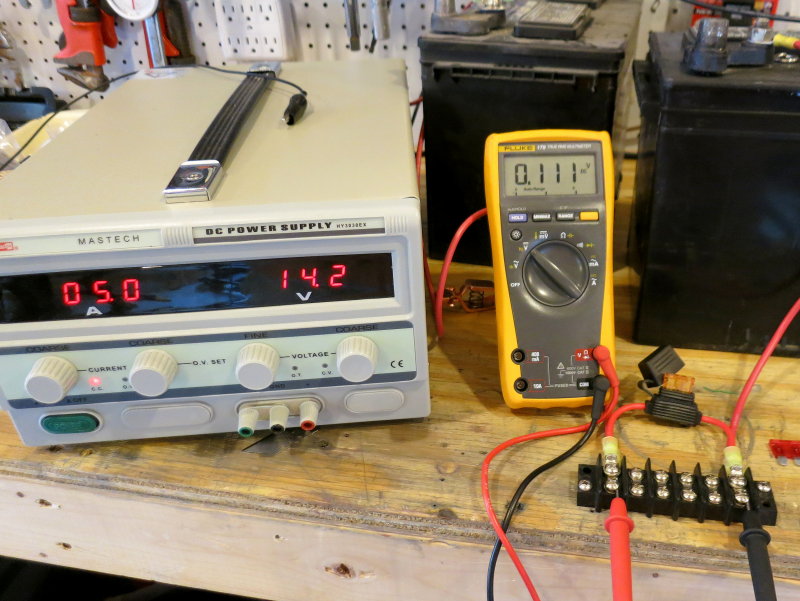
In the photo below I am measuring the voltage drop across the small fuse and in-line fuse holder under a 5A load. This little section of wire, and the fuse, most of it is fuse, is dropping 0.111V at just 5A.
You need to give us something to work with like a diagram, photos or measurements..
Hookay, will take some pix tomorrow. Diagram will have to wait.
Alternator output through the center stud on the isolator.
Appreciate you hanging in here with me. Bizarre stuff. I'd turn this over to a professional if one would ever call back or respond in any way. But there is more diagnosis I can do.
Alternator output through the center stud on the isolator.
Appreciate you hanging in here with me. Bizarre stuff. I'd turn this over to a professional if one would ever call back or respond in any way. But there is more diagnosis I can do.
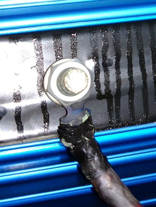
Danger Will Robinson!!!! Look here for your voltage drop & high resistance. This terminal looks badly over heated and burned... Those wires are also pretty undersized for a 90A alternator..
Mystery continues. I let the engine rub for about ten minutes. Then started checking.
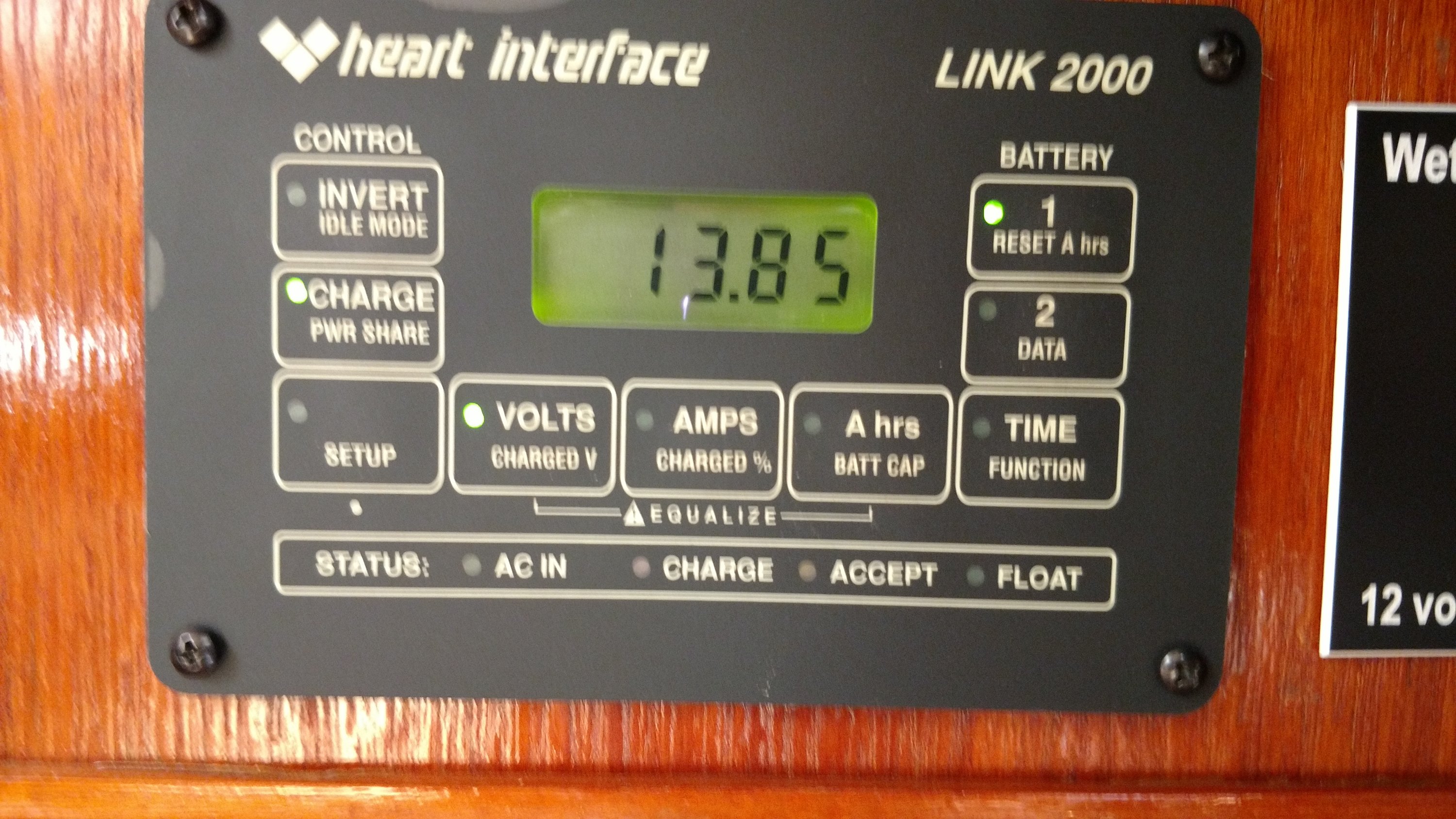
Volts at alternator 15.4
Volts at center stud of isolator 15.4
Volts at house stud 14.7
Volts at start stud 14.6
Volts at start battery 14.5
Volts at house bank #2 14.5
Then I pulled off that suspicious looking lead from the house battery connection at the isolator. It's a bit crispy but I left it alone since I didn't have a ring terminal big enough to fit the stud or a large crimper to crimp it.
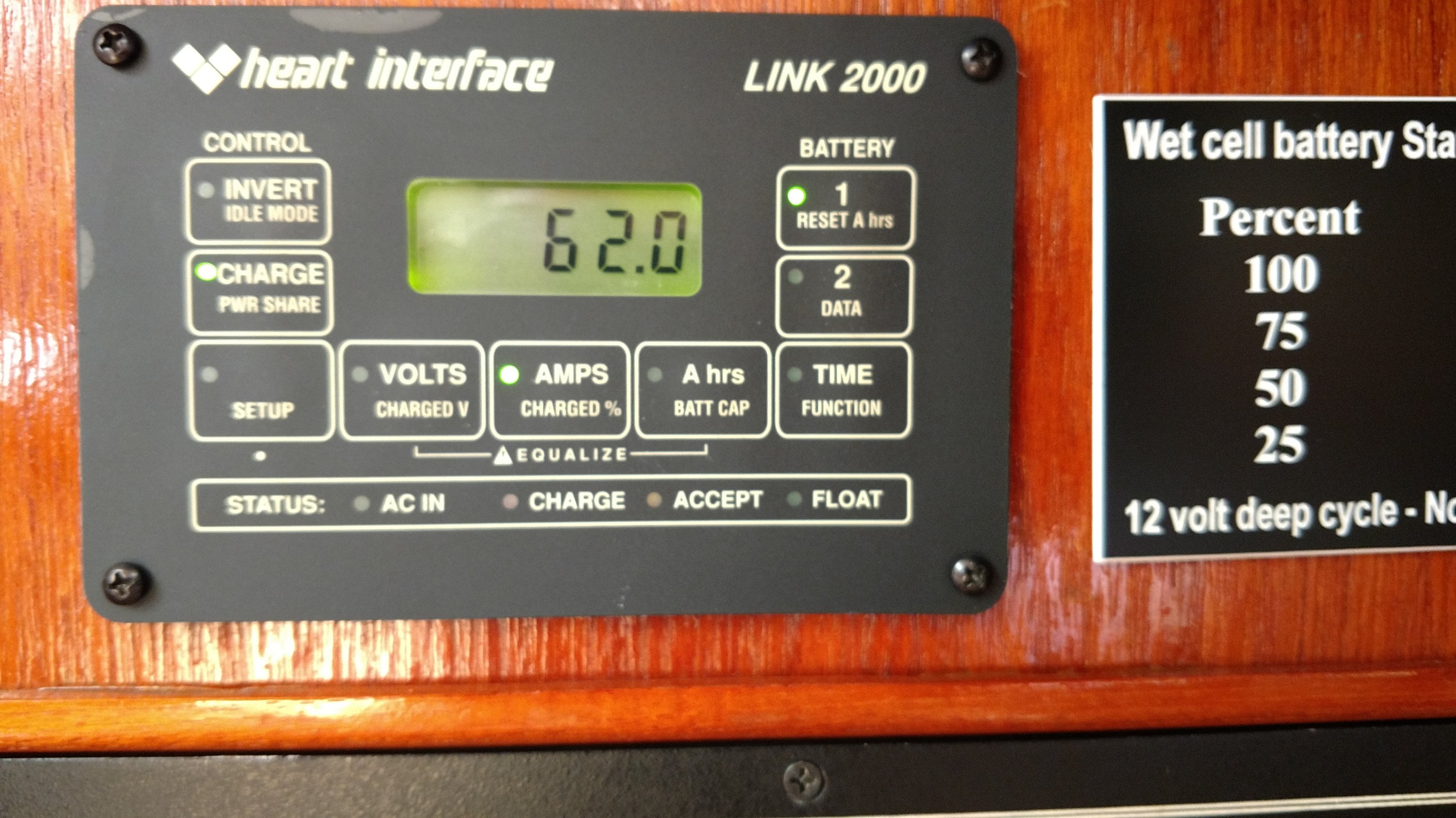
Then I restarted the engine, and lo and behold, I was getting 65+- amps at the house. (when set on ALL)
Now I am at a loss to figure.out why the house is now being charged and the regulator *appears* to be working although the voltage still seems high. And, remember I cooked a brand new Optima start battery.
I'm still very concerned and even more baffled.
Volts at alternator 15.4
Volts at center stud of isolator 15.4
Volts at house stud 14.7
Volts at start stud 14.6
Volts at start battery 14.5
Volts at house bank #2 14.5
Then I pulled off that suspicious looking lead from the house battery connection at the isolator. It's a bit crispy but I left it alone since I didn't have a ring terminal big enough to fit the stud or a large crimper to crimp it.
Then I restarted the engine, and lo and behold, I was getting 65+- amps at the house. (when set on ALL)
Now I am at a loss to figure.out why the house is now being charged and the regulator *appears* to be working although the voltage still seems high. And, remember I cooked a brand new Optima start battery.
I'm still very concerned and even more baffled.
On ALL/BOTH you will not see the voltage disparity because the batteries are in parallel. You will only see a minor cable drop variance at higher currents..
Alternator B+ @ 15.4V - House Positive Terminal @ 14.5V = 0.9V drop @ 65A & this is just too much especially when you realize you've not even tested the negative side of the circuit and that at 80A or 90A this is going to be even worse.
Undersized wire, bad terminations and a diode isolator in the path = BAD...
If you take it off BOTH this 0.9V will now be stacked onto the start battery because you are sensing the house bank and it's path has a LOT of drop under high current. The start battery has almost no voltage drop, because it is accepting minimal current, most of that 0.9V will be seen on the start battery..
Remember it takes CURRENT (house bank) to create voltage drop. The higher the current the more voltage you are dropping. The lower the CURRENT (start battery) the less voltage drop.
This is one reason diode idolators have not been used by competent installers in over 20 years......
Rx
Larger alt B+ & B- wires (You want minimum voltage drop eg: less than 2%)
Feed alt B+ & B- direct to house bank & place a fuse within 7"of positive post
Fuse is sized @ 150% of alternator rating and not above wires max ampacity
Sense voltage at house bank
Place an ACR between house and start banks
Problem solved...
Again, study this drawing below paying close attention to the voltage drops on each section of wire and you will see how easy it's to over charge a start battery with a diode isolator, especially when it is installed at the wrong end of the alt B+ cable and you're sensing the house bank.....
On of the major mistakes installers often made with diode idolators is installing them close to the alt not close to the batteries. Course if you are running cable large enough for the alt output, all the way to the bank, then the best option is to feed the alt direct to house, or a house charge bus, and then use an ACR to charge start...
Now let's look at this same system with a properly installed ACR and wires sized adequately for the alternator to minimize voltage drop... (NOTE: fusing etc. has been left out for simplicity)

Ok, I think I have it. I'm going to keep the start battery switch off on the way back to avoid an overcharge.
You spent a lot of time with me on this and I appreciate the patience and instructions. I think I'm going to tackle this myself. The system was installed by professionals eighteen years ago when the boat was recommissioned. I don't have the confidence calling someone now and trusting them. Besides, if I do it I know what I did.
Thanks again.
That's a very healthy approach. A simple question, albeit long-winded: You're a "regular" here on this forum. Maine Sail has been writing about boat electrical systems for eons, like as long as isolators have been identified as basically dumb things for a healthy charging system. Were you, perhaps, just not aware that you had one of them on your boat? [professional installation notwithstanding...Besides, if I do it I know what I did.
") ]
]No excuse, Stu. I have read them faithfully but have to say that it wasn't a problem until it was. When I replaced the diode isolator to replace a failed predecessor a dozen years ago, I went to a commercial marine electrical place and they sold me this one, all be it a much more heavy duty one. I think the deal is that these are for large motor yachts and commercial vessels that are likely a lot less concerned about some voltage drop. ACR it is! Just when I was getting the punch list whittled down, it grew.That's a very healthy approach. A simple question, albeit long-winded: You're a "regular" here on this forum. Maine Sail has been writing about boat electrical systems for eons, like as long as isolators have been identified as basically dumb things for a healthy charging system. Were you, perhaps, just not aware that you had one of them on your boat? [professional installation notwithstanding...