New Batteries and Switch

ant302

.
Apr 23, 2024
2
Hunter 320 Miami
Inherited the hot mess of batteries below when I purchased the boat 2 years ago. I am looking to replace these with 4 group 24 AGM Odyssey batteries. With some battery bank floor augmentation I can make all 4 fit. Also, I have an additional battery switch that is not in the owners manual and does not control solar. Any idea what this might be for? I do not want to start pulling wires for it without having some idea what it might control.

Any suggestions to make the battery install easier I would greatly appreciate it. I have done a good bit of research but I'm in a bit over my head.

Cheers,
 

Attachments

Jan 7, 2011
4,810
Oday 322 East Chicago, IN
Just a guess, but one switch is a 1-2-both-off switch, usually used to switch the house batteries. You could check and see if wires are attached to both A and B terminals…then trace them back to the batteries…I would guess the two in battery boxes (one with a 2 label) are the house batteries.

The other one appears to just turn on a starter battery (which I would assume is isolated from the house bank). I see that one of the cables from the #2 battery has a label for “start”…so who knows what sort of mess you are dealing with.

You may want to consider what your energy needs are, what sort of sailing you do, and read up on your options. Lithium batteries are popular, but need some special charging.

I personally like the simplicity and bang for the Buck of lead acid Golf Cart batteries for a house bank. Add a starter battery and you could be all set.

I went with 2 6-volt GC batteries (215Ah) in series for 12 volts. Been bullet proof for several years now. I day sail mostly, with an occasional 2 nights on the hook. No solar, but I can get by for 2-3 days with minimal engine use. Refrigeration is my biggest load.
IMG_1923.png

I haven’t even added the starter battery yet…but I will just for redundancy to start the engine if my house bank dies.

But you will need to figure out where those wires go.

Greg
 
  • Like
Likes: Jkutyna
Jun 17, 2022
70
Hunter 380 Comox BC
Difficult to remotely troubleshoot wiring.... suggest tracing the wires from each battery switch.

The house battery should be fused within 18 inches.(7 inches) The easiest way to do this is with an MRBF fuse if you don't have an inverter. Only the battery charger and bilge pump should be connected direct to the battery (each with their own fuse).

Wing nuts are a big no-no on a boat (was this picked up on your survey)? Overall the wiring looks ok. You don't have more than 4 ring terminals to any one stud. The batteries appear to be strapped down which is good.

I'm guessing the battery on the left is your start battery (AGM) and the batteries on the right (flooded) are the house batteries? Depending on manufacturer, they may require different charge voltages. Is your AC shore power charger adjusted for AGM or flooded cells? Ideally, all batteries are the same type with the AC charger adjusted to the appropriate mode (so you're on the right track!).

The positive terminals should be protected by a red rubber boot.

If you retain the flooded batteries, the charger should be located as far as possible from the batteries, as the batteries can release corrosive gas when they charge.

If your 1-2-off switch is wired to start and house batteries, it may be worth considering to a dual circuit OFF-ON switch with an ACR. With this setup, the alternator will automatically charge both batteries. You then only need the AC shore power charger connected to one battery. It is possible that the 1-2 switch is designed for two house banks as well. Can you start the engine with the 1-2 switch in the OFF position?

or

And might as well consider a power monitor...
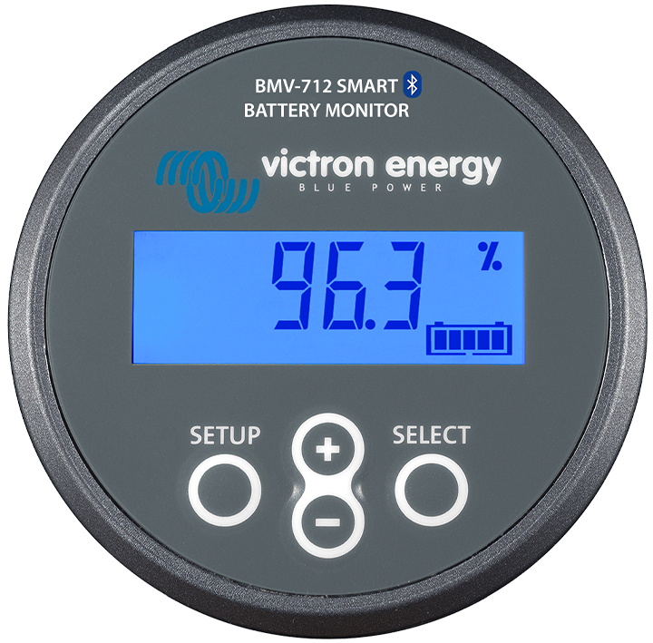


Overall, looks pretty good! I've seen a lot lot worst.
 
Last edited:
Jan 11, 2014
11,480
Sabre 362 113 Fair Haven, NY
The house battery should be fused within 18 inches. The easiest way to do this is with an MRBF fuse if you don't have an inverter. Only the battery charger and bilge pump should be connected direct to the battery (each with their own fuse).
This is incorrect per ABYC 11.10.1.1.1
11.10.1.1.1 Overcurrent Protection Device Location - Ungrounded conductors shall be provided with overcurrent protection device(s) within a distance of seven inches (178 mm) of the point at which the conductor is connected to the source of powermeasured along the conductor seeFIGURE8)
There is an exception:

EXCEPTIONS.
Cranking motor conductors.
If the conductor is connected directlv to the batterY terminal and is contained throughout its entired istance
i n a s h e a t h o r en c l o s u r e s u c h a s a c o n d u i t , j u n c t i o n b o x . c o n t r o l b o x . o r e n c l o s e d p a n e l t h e o v e r c u r r e n protection shall Be placed as close as practicable to the• battery not to exceed 72 (183c m)
(sorry for the funky text, copied from a pdf file.)

Briefly, the fuse must be within 7 inches of the battery terminal unless the cable is fully enclosed in a conduit or sheath to be ABYC compliant. An MRBF fuse will meet the requirement for lead acid batteries, however it will not meet the requirements for a LFP battery. Starting batteries do not need overcurrent protection, however, it is a good idea to add it anyway.
 
  • Like
Likes: marcham
Oct 22, 2014
21,153
CAL 35 Cruiser #21 moored EVERETT WA
As said, not bad. The ideas shared support best practices consistent with marine use of batteries.

My eyes were drawn to the way the batteries were positioned in the compartment. It appears the straps hold the batteries in the black boxes. But the boxes look like they can slide about the compartment. The compartment looks to be under a seat on one side of the boat. This arrangement could have the batteries sliding about while sailing and the boat may heel a little quicker on one side, assisted by the weight of the 3 batteries.

While there is often no simple solution, it is desirable to have the batteries as low and centered near/on top of the keel. You want to secure the batteries so that they can’t move/shift as the boat is sailing. This often means building a box to coral batteries and securing it to the hull.

You indicated getting 4 g24 batteries. Not a bad idea. It might help to identify you power needs. Add up the Amp Hour demand you think may be used. Then identify how you will replace the energy used. This will guide you to the size of battery storage needed. It may be 3 g24’s or 6 8D’s (not a good solution for a small boat as that many may not fit or put a permanent heel on the boat).
 
Feb 26, 2004
22,783
Catalina 34 224 Maple Bay, BC, Canada
Basic Battery Wiring Diagrams This is a very good basic primer for boat system wiring: Basic Battery Wiring Diagrams

This is another very good basic primer for boat system wiring: The 1-2-B Switch by Maine Sail (brings together a lot of what this subject is all about)
http://forums.catalina.sailboatowners.com/showthread.php?t=137615

This is a newer primer for boat system wiring design with a thorough diagram: Building a Good Foundation (October 2016)
Building a DC Electrical Foundation

The Short Version of the 1-2-B Switch Stuff: Electrical Systems 101 This is a link to the Electrical Systems 101 Topic, reply #2
 
  • Like
Likes: jssailem
Feb 14, 2014
7,450
Hunter 430 Waveland, MS
Any suggestions to make the battery install easier I would greatly appreciate it.
Do you have the H320 Owners Manual?

If not, I do have it.

Its shows how your batteries where set up OEM.

Example:
320 12 vdc.png


Jim...
 

ant302

.
Apr 23, 2024
2
Hunter 320 Miami
Basic Battery Wiring Diagrams This is a very good basic primer for boat system wiring: Basic Battery Wiring Diagrams

This is another very good basic primer for boat system wiring: The 1-2-B Switch by Maine Sail (brings together a lot of what this subject is all about)
http://forums.catalina.sailboatowners.com/showthread.php?t=137615

This is a newer primer for boat system wiring design with a thorough diagram: Building a Good Foundation (October 2016)
Building a DC Electrical Foundation

The Short Version of the 1-2-B Switch Stuff: Electrical Systems 101 This is a link to the Electrical Systems 101 Topic, reply #2

Immensely helpful. Thank you.