Solar Voltage

walt

.
Jun 1, 2007
3,517
Macgregor 26S Hobie TI Ridgway Colorado
The question is.. Lets say we have panel that has a open circuit voltage of 100 volts (or a maximum power point voltage of 100V) and in full sun produces 5 amps and also has a short circuit spec of 5 amps.

How much power is produced by the panel if its connected directly to a battery rather than through an MPPT controller. Or, if the controller is damaged and looks like a wire, what happens.

The panel is capable of 500 watts. However with nothing connected to the panel, current is zero so the panel is producing zero watts (I is zero so P is zero). The panel is also producing zero watts if shorted even though the current is 5 amps (V is zero so P is zero)

The panel looks "mostly" like a constant current source (link at the bottom).

Put the panel on a MPPT controller with a load capable of taking all the power produced. The controller adjusts the "internal" load to operate the panel at its maximum power points of V = 100V and I=5 amp so power produced by the panel is 500 watts. And of course, current to the battery could be significantly higher than the solar panel current.

Put the same solar panel directly on a 24 volt battery. The panel looks like a constant current source so the current is still 5 amps. This is only enough current to raise the battery voltage slightly. The panel now operates at 24 volts and 5 amps so the panel is now producing 24V*5A = 120 watts.

Put the same panel directly on a 12 volt battery. Still constant current at 5 amps, still only enough current to barely raise the battery voltage. The panel is once again at the battery voltage so the power produced is 12V*5A = 60 watts.

This somewhat illustrates why an MPPT controller gets more power out of a panel than a PWM controller. The solar panel current for either type of controller is the same. PWM operates the panel at the battery voltage but the MPPT controller can operate the panel at a higher voltage and will actually search for that optimum voltage. Same current but higher panel voltage is higher power produced.

 
Last edited:
Jan 11, 2014
11,869
Sabre 362 113 Fair Haven, NY
Put the same solar panel directly on a 24 volt battery. The panel looks like a constant current source so the current is still 5 amps. This is only enough current to raise the battery voltage slightly. The panel now operates at 24 volts and 5 amps so the panel is now producing 24V*5A = 120 watts.

Put the same panel directly on a 12 volt battery. Still constant current at 5 amps, still only enough current to barely raise the battery voltage. The panel is once again at the battery voltage so the power produced is 12V*5A = 60 watts.
The part that is not evident in your analysis is the battery's resistance. There is still 500 watts of power being applied to the battery, the internal resistance of the battery causes the voltage to drop. Your explanation sort leads one to believe 440 watts (in the 12v example) just disappears, it doesn't, it converts to heat, it breaks down the sulfates, and if the voltage is high enough it starts breaking the water molecules. Most of those things aren't very good for batteries.

So, in an installation if an undersized controller is installed, as was the case in Rod's Pro Boat article, the controllers resistance would be too high, causing it to heat up and thus increasing resistance until either a fuse blew or the wire melted. If the system is designed properly with proper sized wires and controller, there should be no issue. Since internal wiring in a panel is already optimized to produce the most power, then any internal failure should only reduce the current and not increase it.

In the end, I think we are both agreeing that a circuit protection is not needed between the panel and the controller if the system is designed and wire properly for the power being produced. One advantage to adding a switch or circuit breaker between the panel and controller is convenience, no need to throw a blanked over the panel.
 
  • Like
Likes: JoeWhite
Mar 26, 2011
3,539
Corsair F-24 MK I Deale, MD
I don't know if this will help or confuse:

The maximum power point is at about 16.5 V on this panel. Charging at this voltage with an MMP charger will be more efficient that at 12 V. But there are a few falsies in this simple argument.
  • The battery will be charging at more than 12 V unless it is dead flat and cold. At 80 F and 60% SOC (as low as most of use go) it is 12.3 and the voltage will be about 12.6 average thought most of the cycle. I had MPPT on my last boat, but I have only one panel and a PWM controller on this one. Most of the time it is close to or over 13 V.
  • As soon as the panel starts pushing in electrons the voltage will rise considerably. Thus, charging voltage will be more like 12.5-13.0.
  • The voltage at the charger may be less than at the panel by 0.2-0.3 volts due to wire resistance.
  • The V-A chart is at 70 F. PV panel voltage and efficiency drops with increasing temperature.The peak power voltage may be only 17-18 V at operation temperature.
Yes. MPPT is more efficient, but only about 10% in the real world, not the 20-30% that is often touted. It's complicated.

And remember with a battery that you are getting Ah out. You put power in at about 0.4-0.7 V higher than you get it out, resulting in a hysteresis loss. Both internals and external resistance play a part.

Not worth getting too hung up on. More panels in the right places solve most woes.

I find the toughest problem is the winter battery voltage drop. Many electronics just shut off at 70% SOC. They think the battery is dead. The tiller pilot is one.


Johann

.
Jun 3, 2004
438
Leopard 39 Pensacola
The part that is not evident in your analysis is the battery's resistance. There is still 500 watts of power being applied to the battery, the internal resistance of the battery causes the voltage to drop. Your explanation sort leads one to believe 440 watts (in the 12v example) just disappears, it doesn't, it converts to heat, it breaks down the sulfates, and if the voltage is high enough it starts breaking the water molecules.
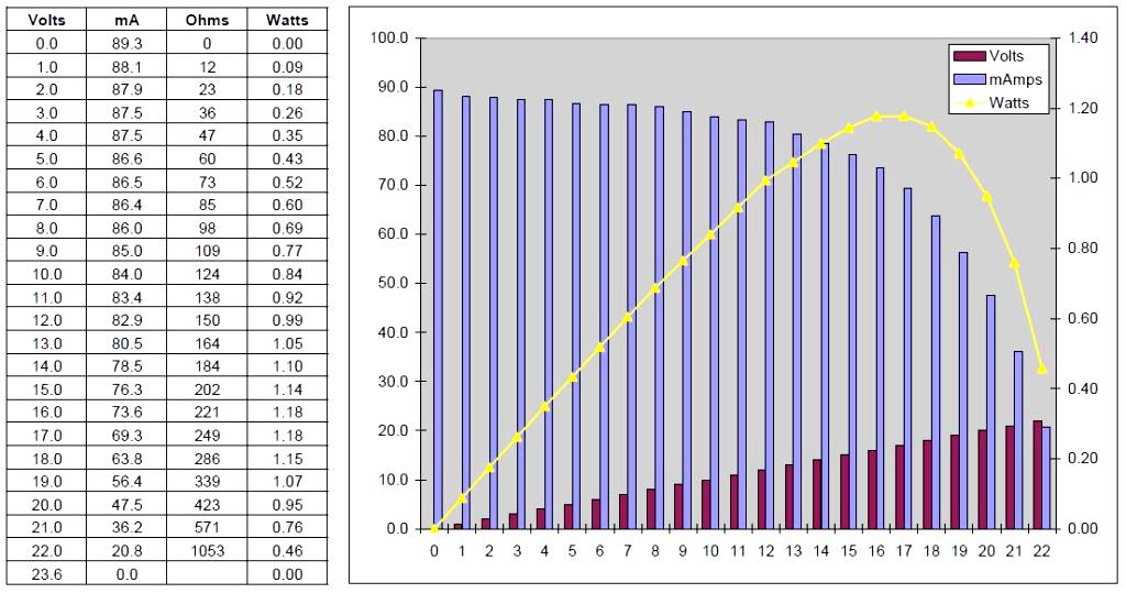
Walt is correct here. The panel will not produce 500W at 12V, or at any voltage below or above its Vmp. This is the entire point of having an MPPT. Look at the I-V curves for any panel and you will see how the power output changes at various voltages. The panel outputs a constant current and the power is determined by the voltage. Connected to a 12V lead battery, that isn’t full, the voltage will be initially limited and thus the power will be low. As the battery becomes more full, the voltage will continue to rise until the bad things you mentioned begin to happen.
 
  • Like
Likes: walt
Jan 11, 2014
11,869
Sabre 362 113 Fair Haven, NY
Connected to a 12V lead battery, that isn’t full, the voltage will be initially limited and thus the power will be low. As the battery becomes more full, the voltage will continue to rise until the bad things you mentioned begin to happen.
For me the confusing part is what is limiting the voltage. The panel doesn't limit the voltage, the circuit and more specifically the resistance of the load attached to the panel limits the voltage, in this case the battery's SOC. (Assuming the panel is in perfect sunlight.) This makes sense to me, because there is nothing inherent in panel that could control the panel's output, i.e., the panel is basically dumb, it will keep producing as much amperage as it can and will drive the voltage up to get the load to take it. The controller then, tries to match the battery's need with the solar output for most efficient charging, raising or lowering voltage to provide amperage the battery can take.

While the panel's voltage will increase, there is a maximum voltage and amperage it can attain. In that sense it is a self-regulated power source and does not need to be fused at the panel because an appropriately sized wire can be used, unlike a battery where the entire capacity of the battery can be discharged in fractions of a second, exceeding the ampacity of the wire.
 
  • Like
Likes: Johann
Mar 26, 2011
3,539
Corsair F-24 MK I Deale, MD
... While the panel's voltage will increase, there is a maximum voltage and amperage it can attain. In that sense it is a self-regulated power source and does not need to be fused at the panel because an appropriately sized wire can be used, unlike a battery where the entire capacity of the battery can be discharged in fractions of a second, exceeding the ampacity of the wire.
Panels can and do short, more often than many devices. Obviously, it must be fused near the battery, since controller are not normally wired through the main panel. You are correct in that it can't generate enough power on its own to burn the supply wires. As you say, in that way, it is self-regulating. But if there is a battery in the circuit ....
 
Jan 11, 2014
11,869
Sabre 362 113 Fair Haven, NY
Panels can and do short, more often than many devices. Obviously, it must be fused near the battery, since controller are not normally wired through the main panel. You are correct in that it can't generate enough power on its own to burn the supply wires. As you say, in that way, it is self-regulating. But if there is a battery in the circuit ....
Right, if for some reason the panel was wired directly to the battery or to the DC+ bus, then over current protection would be needed at the battery end of the wire but not the panel end. No OCP is needed between the panel and controller and the controller needs OCP at the battery end of the wire, not the controller end of the wire. There was some disagreement about this earlier in the thread.
 

walt

.
Jun 1, 2007
3,517
Macgregor 26S Hobie TI Ridgway Colorado
I think what you said is correct, just to add some details.

Solar panels look like constant current for a fixed sun power flux. Solar panels are not constant power, as mentioned, you only get max power when you bias the panel at its Vmp. Take a look at the curves again in this link PV panel -a current source or voltage source?

The "current" curve vs operating voltage shows the short circuit current at 0V and you will notice that the current stays at the same level as the panel voltage increases. This is what is referenced as "constant current". Power is V*I so on the power curve, you can see the generated power go up. Current is constant but as the voltage rises, power goes up until the Vmp is reached.

Battery impedance is brought up and is important. A battery of course has a very low impedance. The little more difficult concept is that the solar panel has a fairly high impedance. Example, with a battery, a very small change in voltage can produce a very large change in current. But the panel is just the opposite, a lot of change in voltage produces almost no change in current. So if you connect a solar panel directly to a battery, the battery impedance completely dominates and the panel operates at the battery voltage. And since the panel is constant current at a fixed sun flux, that is the current the panel puts out. If the battery voltage is way under the panel Vmp, the panel will also operate at way under its rated power.

And in our example before where we connected a rated 100 volt panel to 12 volt, the panel power is way down but it still put out 5 amps and unregulated, that will damage any sort of battery we are talking about here.
 
Last edited:
  • Helpful
Likes: Johann

walt

.
Jun 1, 2007
3,517
Macgregor 26S Hobie TI Ridgway Colorado
If we are getting into the nitty gritty.. there could be a reason to fuse between the panel and the controller.

You guys know that the parasitic power loss in a wire is given by P = I * I * R (ie, current squared times R). So each time I is cut in half, R can go up by a factor of four times for the same power loss in the wire. If you have a panel that say operates at 48 volts going into a controller feeding a 12V battery, the current on the panel side is going to be four times smaller than the current to the battery.

So way different wire gauge runs could be used between the panel to controller compared to from the controller to the battery. A higher voltage panel can use smaller wires with the same wire parasitic power loss so the benefit of lighter weight and less expensive.

Remember you are generally always fusing to protect the wire. Anytime you change wire gauge from larger wire to smaller wire, you need to add in a new fuse appropriate for the smaller wire.

So in the case of our high voltage panel, we could have considerably smaller gauge wire that might burn up if a controller turned into a dead short. In this nit pick case, a fuse sized for the smaller wire between the panel and the controller and placed close to the controller "might" be a good idea.
 
Last edited:
Dec 4, 2023
109
Hunter 44 Portsmouth
Regarding the above link, we are talking about if fuse on the input side of the controller can protect against fire. My answered in the case above is not since there is excessive voltage not excessive current. This write up is from a 2013 magazine not from a technical review. Technology has improved and lessons learned.
The real problem is caused by a want-to-be solar panel installer with just enough knowledge to make trouble.
This is not normal case if installed properly.
I dismiss this writeup as a convincing proof for anything. You can comfortably ignore it.
Hi Joe,

I don’t want to come off as rude, but did you read the article?

The crux of the issue in the article was a solar controller that failed in a catastrophic way that allowed panel voltage (in this case significantly above anything a 12V system would ever see, it wasn’t talking about 16V panels in this install) to pass through the controller and apply directly across the batteries.

The article didn’t touch on fusing. We both agree that fusing wouldn’t address this case. The point of the article was that it is safer to keep solar installations <50V and use high quality solar controllers.

A side point was that Rod was expressing appreciation to the safety of LiFePO4 chemistry in how they were able to experience a catastrophic failure like this and not enter thermal runaway.
 
Mar 26, 2011
3,539
Corsair F-24 MK I Deale, MD
Right, if for some reason the panel was wired directly to the battery or to the DC+ bus, then over current protection would be needed at the battery end of the wire but not the panel end. No OCP is needed between the panel and controller and the controller needs OCP at the battery end of the wire, not the controller end of the wire. There was some disagreement about this earlier in the thread.
^^ Yes.
 
Mar 26, 2011
3,539
Corsair F-24 MK I Deale, MD
... Battery impedance is brought up and is important. A battery of course has a very low impedance. The little more difficult concept is that the solar panel has a fairly high impedance....
A minor point but ...

Impedance and resistance are the same thing for a DC circuit. We're not talking AC. Just increase someone was confused.

The battery has very low resistance, but as soon as a charging current is applied, the voltage jumps ... considerably. This is not true resistance, more a matter of chemistry. For example, a battery must be allowed to rest and stabilize after charging before an accurate SOC can be obtained. The point is that the battery voltage (SOC) cannot be measure while a significant charging current or load is applied.
 

walt

.
Jun 1, 2007
3,517
Macgregor 26S Hobie TI Ridgway Colorado
Sort of related to this thread.. I will share since I thought it was very interesting.

I live at 7000 ft elevation and my neighbor has an ambient weather network station that monitors the sun flux in watts per square meter. Solar panels often use 1000 watts per square meter as the peak sun flux for their power spec. Satellites outside the atmosphere measure the peak flux at 1361 watts per square meter.

At 7000 ft elevation, the neighbor's sensor will often measure 1000 w/m**2 on a sunny day. However, the other day, I was looking at his record (available on a web site) and it showed

time (PM) flux
1:05 1094 w/m_sq
1:10 864
1:15 1177
1:30 1281
1:40 284

Wow.. 1281 w/m**2 which is not much less than what is outside the atmosphere. I had checked two weather stations close by, all had similar peaks so I think its accurate.

Neighbor ( used to be involved with solar measurements at NOAA and NREL so likely accurate) had this reason for the crazy high number. Near solar noon if cumulus clouds are positioned just right will reflect additional radiation to the ground - readings could be 5-15% higher than a pure blue bird day.

The cloud theory sounds accurate because just 10 minutes after the very high peak, the power dropped way off.

Interesting from our perspective because if you had a fuse or system without much margin for the current spec from the panel, there could be cases where the panel current could be at least 20 percent higher than what's in the spec.

Anyhow.. interesting enough to take the time to post.
 
  • Like
Likes: thinwater
Jan 11, 2014
11,869
Sabre 362 113 Fair Haven, NY
Our panels are rated under a standard condition. If the solar flux is greater, then the panel output should also be greater. From time to time, my panels will excede their rated capacity of 150 watts, but only by 5-10 watts and I suspect for only a short time.

In the kind of modest arrays most of us have, 300w to 500w the short burst should not be a big deal and probably within the margin of error for the wires. However, if we have the kind of array that some full time cruisers have, 1KW and above, a modest 10% increase could be more concerning.
 

dLj

.
Mar 23, 2017
3,587
Belliure 41 Sailing back to the Chesapeake
Interesting discussion - over the past year of running my panels, I've never seen them even reach their stated output - close a few times, but certainly never more...

dj
 
May 7, 2012
1,404
Hunter e33 Maple Bay, BC
Interesting discussion - over the past year of running my panels, I've never seen them even reach their stated output - close a few times, but certainly never more...

dj
Victron MPPT Connect app has a feature that provides a 30 day history of various data including - P Max - maximum power for the day. On 3 days the boat must have been healing in the absolute right direction to capture more than the 170W rated output.
1723474690583.png
 
  • Like
Likes: Johann

Johann

.
Jun 3, 2004
438
Leopard 39 Pensacola
Interesting discussion - over the past year of running my panels, I've never seen them even reach their stated output - close a few times, but certainly never more...

dj
I think a lot depends on the panel. I have seen over 400W from my 335W Panasonics quite often with clouds. But my 200W Rich panels lag behind significantly. I believe I have only seen them reach their rating twice since installing them last year.
 
Nov 21, 2012
630
Yamaha 33 Port Ludlow, WA
No OCP is needed between the panel and controller and the controller needs OCP at the battery end of the wire, not the controller end of the wire. There was some disagreement about this earlier in the thread.
The disagreement is still alive. :deadhorse:My point remains that the controller can output power into a dead short. OCP at the battery is irrelevant, as the controller is the power source.

Consider the picture below.
1723738313062.png


Fusing the panels was not the point, although the discussion was interesting. We are in agreement that they do not need to be fused in most circumstances. A disconnect is a good idea though.
 
  • Helpful
Likes: jssailem