if you wire like centerline proposes - you loose any isolation between house and start - you would have one bank (no need for the echo) and if you drain that bank on a trip at anchor or sailing with radar, frige.on.... you will be unable to start the motor.
Old Boat - Old wiring - old batteries
- Thread starter jssailem
- Start date
Hi John, I know how are boat is wired and all changes that I have made I've done myself. As far as offering advice, I would begin with laying out in detailed specifics what it is you want your system to do. That will describe how much power you will need. Lots of opinions as to whether 12v or 6v batteries is the way to go. Our boat came equipped with 12v batteries, so my choice makes it easier.
I could convert to 12v, but what I have works just fine and meets our needs. Seems silly to go to the expense of changing over. Hunter, in my mind, did a good job of designing the AC/DC requirements for our boat. However they did it, I'm sure it began with a detailed specification of both AC and DC sides.
I would be happy to answer any questions, but keep in mind I am not a marine electrician. Most of my answers would be anecdotal.
This is correct... IF you only have 2 batteries on board, I agree one of them should be a dedicated starting battery... but for a boat the size of Johns, and his intended purpose, I feel there should be at least (4) 6v GC batts or (2) 12v golf cart batts, something like the T1275, for the house bank, minimum, in addition to the starting battery.... with an automatic charge relay in the system for isolation and automatic, dependable charging of both banks...if you wire like centerline proposes - you loose any isolation between house and start - you would have one bank (no need for the echo) and if you drain that bank on a trip at anchor or sailing with radar, frige.on.... you will be unable to start the motor.
Last edited:
Hi John, had the same problem when I installed the Link1000 on our boat a few years ago. Lots of ground cables and not enough room on the battery post. So, what I made was a buss out of brass bar in the shape of a cross that I purchased at a local metal fabrication shop for about $3, which gave me four mounting points plus a fifth in the center. Hard to tell from the photo, but I mounted the buss bar on the battery shelf, one cable from the ground post terminated on one side of the buss bar, with several ground cables terminating on the other sides. Some had two; one on top one underneath. This has worked out well and solved the post problem.Having more than 4 terminations on one post is a no no. so how to do it with the wiring limits I have is challenging me.
In order for the Link1000 to deliver accurate battery stats required a shunt. The shunt had limited terminal space, too. It was important to have the single main ground from the boat to one side of the shunt and all other ground cables to the other side of the shunt. The brass buss bar made that possible.
Attachments
-
 275.7 KB Views: 231
Last edited:
Our first boat had two group 24 deep cycle batteries. Rather than dedicate one battery for starting I made it a point to keep the main battery switch to "Both" for charging while connected to shore power, and select either battery 1 or battery 2 when heading out so that one battery remained unused for the purpose of starting. If it was an odd day when heading out I would select battery 1, even battery 2. Never ended up with a battery unable to start the engine.This is correct... IF you only have 2 batteries on board, I agree one of them should be a dedicated starting battery.
yes, it can be done that way.. and a couple of other ways that would accomplish it, but with the dependable equipment that is available today and its relativly low cost, there is little reason the do it the old fashioned way... which could cause other more expensive problems if one forgets momentarilyOur first boat had two group 24 deep cycle batteries. Rather than dedicate one battery for starting I made it a point to keep the main battery switch to "Both" for charging while connected to shore power, and select either battery 1 or battery 2 when heading out so that one battery remained unused for the purpose of starting. If it was an odd day when heading out I would select battery 1, even battery 2. Never ended up with a battery unable to start the engine.
 ....
....You have a lot going on here. Make a power budget and also think about future installs like maybe a windlass if you dont already have one. Figure out how you want to use "the system". Do you care if electronics drop out when you start the engine? That's a big hitter when configuring batteries switches etc. Do not make multiple connections to the batteries. (Except maybe bilge pump). Configure off batt busses with fuses at the batt. Once your budget is done, you can select wire sizes and remember wire sizing takes the whole circuit into account. Pos and neg..then size fuses to protect the wire (not the equipment). The mystery "echo" box is most likely an isolator that was commonly used in the "old days". A box with back to back diodes with each battery to each cathode and the charging source connected to the anodes which are connected together. This allowed more than one battery to be charged without electrically tying them together. Problem is each diode drops ~ 3/4 volt so batteries were never getting fully charged. A competent electrician could rig the alternator to sense at the battery... Get rid of it...Stu's links probably has good info on a budget!
Most of your wiring should be reusable, but a couple of observations from USPS Electrical course and personal experience as an Electrical Engineer:
1. Get a good ratcheting crimping tool (or risk the cheap harbor freight) and instal new terminals. You can do pretty good crimps with the cheaper hardware store versions, but you have to crimp hard and multiple points on the barrel of the terminal. Silicon Sealant added would be good if you do not use the very expensive terminals with sealant in them.
2. Change to Red for your positive cables and wires, or put on a section of red heatshrink tubing on both ends (or Red tape preferably overlaid with clear heat shrink. (also
Good luck with your new install. There are tutorials on line. Look up ABYC standards. here is an intro: http://goo.gl/Lx69oQ
and another: http://goo.gl/rhKc3I
Here is a good Color code chart ( one in the USPS manuals too) :https://goo.gl/ZR8t9x
Last edited:
I have never used the silicon sealant for crimp connections, but I do use the Dow 111, which is a very thick silicone grease. I dip the end of the bare wire into it then insert and crimp.... it keeps all the moisture out of the connection and so there is never any corrosion. I highly recommend it for all connections..Most of your wiring should be reusable, but a couple of observations from USPS Electrical course and personal experience as an Electrical Engineer:
1. Get a good ratcheting crimping tool (or risk the cheap harbor freight) and instal new terminals. You can do pretty good crimps with the cheaper hardware store versions, but you have to crimp hard and multiple points on the barrel of the terminal. Silicon Sealant added would be good if you do not use the very expensive terminals with sealant in them.
2. Change to Red for your positive cables and wires, or put on a section of red heatshrink tubing on both ends (or Red tape preferably overlaid with clear heat shrink. (also
Good luck with your new install. There are tutorials on line. Look up ABYC standards. here is an intro: http://goo.gl/Lx69oQ
and another: http://goo.gl/rhKc3I
Here is a good Color code chart ( one in the USPS manuals too) :https://goo.gl/ZR8t9x
I'm sure you already know, but for those that dont,... dielectric grease is 100% silicon grease, but with a different label, and silicon grease is waterproof and NOT at all hygroscopic like nearly all common grease is... its good for making ling life connections in damp environments...
No grease here. Always use adhesive lined heat shrink. If the wire has to take a bend close to the termination, then install it and then shrink it.
#1 Remove dead batteries and label where wires came from. Clean up battery compartment.Wanting to get through to winter when I plan to do complete electrical refit.
#2 Trace those wires to the source & relabel if necessary
#3 If wires are undersized, corroded or wrong color for the load or charging device replace them with proper size and color. Red = DC Positive, Black or Yellow = DC Negative. Almost always easiest to just rip it all out and start from scratch.
#4 Replace all battery cabling all they way from starter and engine to switch and batteries.
#5 If battery switch is more than 10-15 years old replace it.
#6 Crimp all terminals with the proper crimp tool. None of the pictured crimps were made properly
#7 All wires connecting to the house batteries (maximum of four wires per terminal but preferably 3 or less) must have fuses.
#8 If you don't have access to a proper battery lug crimper, and hammer crimps are not "proper", measure and spec lugs carefully and have genuinedealz.com make your cables.
Bonus:
Use a negative busbar, positive switched busbar and positive unswitched bussbar (bilge pump etc.) to keep the battery terminals uncluttered.
Label every wire using a label maker and clear heat shrink.
Run alternator direct to new house bank.
This is most likely a diode isolator. Rx = Remove it and trow it in the dumpster....The charging supply appears to come from the unit I'm calling an "Echo" unit. This appears to be from 40 years ago and looks to me to be functioning like an echo charger. The only wires connected to this thing are the two positive large wires from the batteries, a wire from the alternator, and a large gauge wire to the start motor.
As said before a diode isolator needs to have the voltage regulator boosted to compensate for the extra voltage drop.
If you are taking the isolator out , be sure to check the voltage from the alternator and set it back to normal if necessary. Check before you take it out on all terminals to know what you have. Then check after removal.
If your batteries at the same types and the voltage is set right, a diode isolator is a good solution. Reliable, as it has much fewer parts.
Different types of batteries and/or different charging sources (solar, etc) would be best served by a much more expensive charge controller system.
Hi John, I need to update a couple of things from my previous post and pics. The first part is that when I installed the Link1000 it included a shunt. This shunt has two posts, one for all ground cables or ground sources incoming to the shunt. The other post was for the main boat ground outgoing from the shunt. A better picture of this arrangement is as follows:
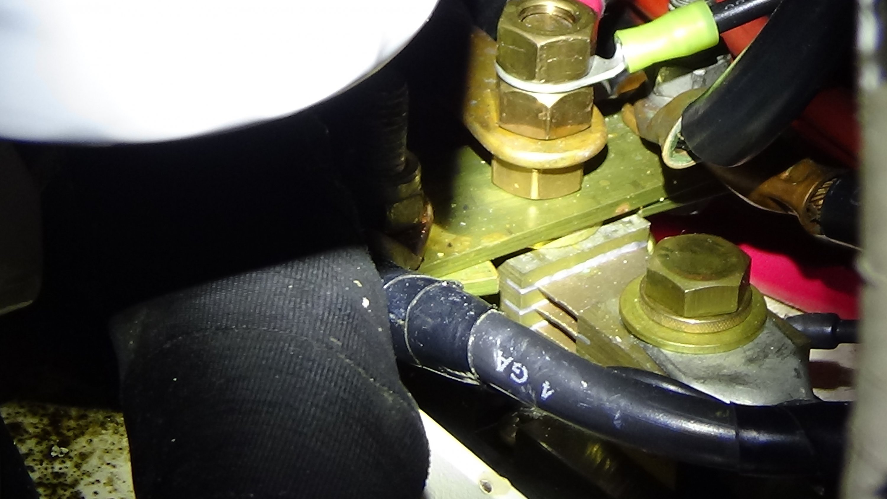
In the above picture what you see is the shunt mounted on the battery shelf. The nearest bolt head is the mount for the main boat ground and is the only ground cable connected to this shunt post. The one next to it that has three nuts is the shunt post where all incoming appliance ground cables mount. That brass bus bar that I made is beneath the lowest nut and it mounts on the shunt post where all incoming ground cables mount. As you can see in the picture two ground cables connect to the right side of the bus bar and two on the left.
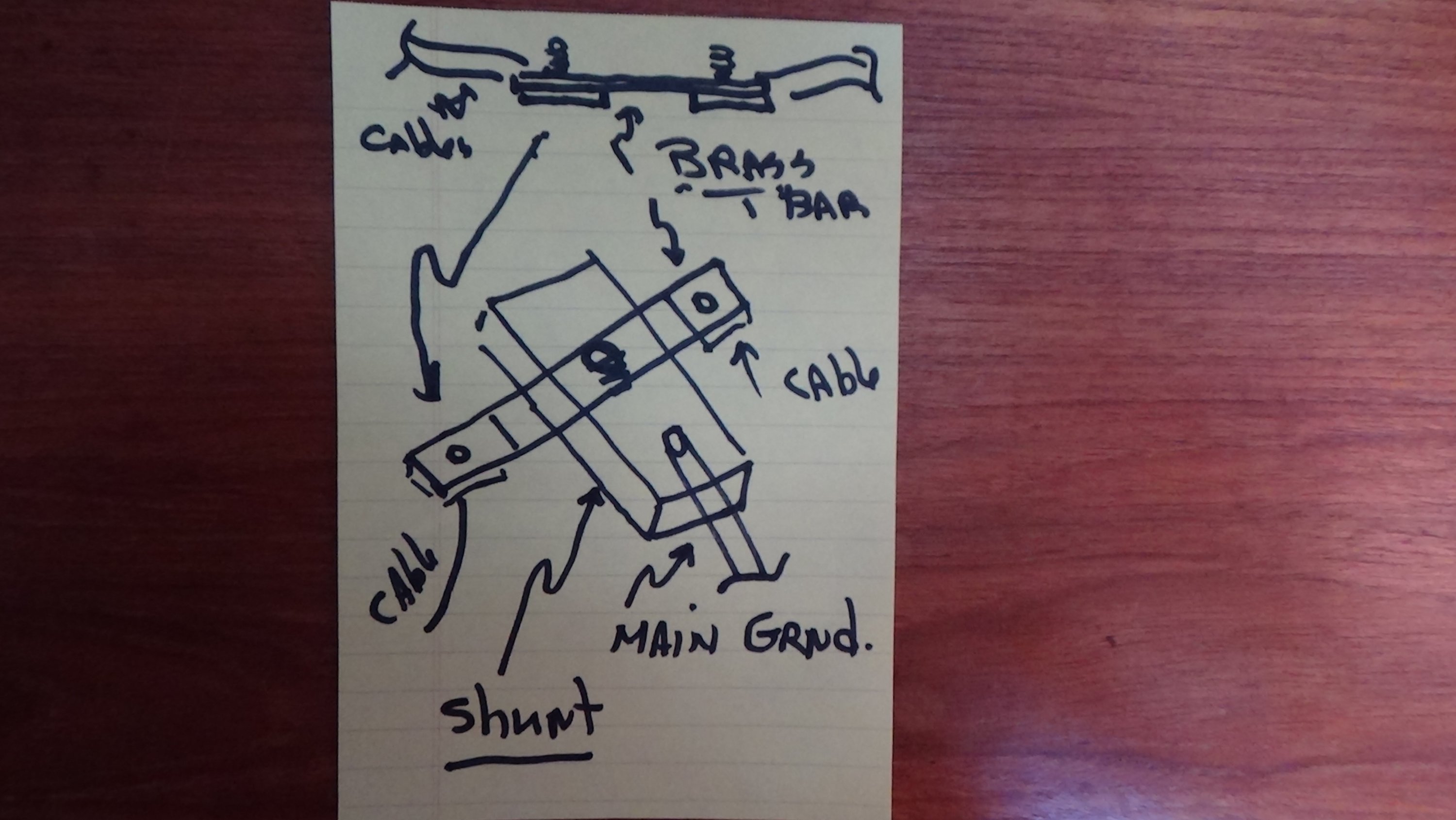
The drawing below shows the "T" bar that connects to the shunt. I placed the small square pieces of brass bar underneath and on either side of the main bar to help prevent the main bar from rotating. Not that sophisticated, but it works and I have a Link1000 that delivers a very accurate battery state.
In the above picture what you see is the shunt mounted on the battery shelf. The nearest bolt head is the mount for the main boat ground and is the only ground cable connected to this shunt post. The one next to it that has three nuts is the shunt post where all incoming appliance ground cables mount. That brass bus bar that I made is beneath the lowest nut and it mounts on the shunt post where all incoming ground cables mount. As you can see in the picture two ground cables connect to the right side of the bus bar and two on the left.
The drawing below shows the "T" bar that connects to the shunt. I placed the small square pieces of brass bar underneath and on either side of the main bar to help prevent the main bar from rotating. Not that sophisticated, but it works and I have a Link1000 that delivers a very accurate battery state.
I think I read this a a 1974 vintage boat. When I did some rewiring on my 1985 boat, I cut open several wires well down the line, 5 to 10 feet from terminals and found plenty of corrosion. I dont think I would reuse much, if any, of that bosts old wire.Most of your wiring should be reusable,
Another short story. Back in about 2004 when our original 1991 Heart Interface 1,600 watt charger/inverter was reaching the end of its life I posted on this site my plan to replace it with an Xantrex 2,000 watt unit. To my surprise and without any solicitation, I received a post reply from Eddie, then Hunter Marine's go-to guy for customer service support. He recommended that I go with the Freedom 25. Much more P42 system friendly, he said. I followed his advice.
Just by chance, I went on Xantrex's online store where they sell factory certified refurbished products and found a Freedom 25 for 60% off retail. I had them ship it to Semi-ah-moo, our marina at the time and installed it myself with a few minor wiring modifications. I took the old, but still working, unit to Pacific Marine Exchange in Bellingham where they sold it on consignment for $350, my cut.
The new Freedom 25 looked brand new when I opened the box. It is a 2,500 watt, 130 amp combi inverter/charger. Awhile later I installed the Link1000 interface that provides stats on DC power charging and consumption. This system has performed flawlessly ever since, working with our two 8D AGMs to supply our boating power needs.
So John, if you can work it into your electrical boat budget, I highly recommend that you include an inverter function to your boat. Comes in handy for small AC appliances, such as laptops, coffee grinders, CD/DVD players, electric toothbrush, etc. As an alternative, Walmart carries small inverters that plug into a 12v socket. We have two on board that we use for our laptop, CD player and electric toothbrush. They work quite well and inexpensive. I installed a 12v socket in each cabin just for that purpose, so when guests are on board they have a way of keeping their assortment of devices charged as well as our own.
Most local auto parts stores carry the 12v socket. The one I like is: http://www.ebay.com/itm/12V-Car-Tru...749519?hash=item210bac1c0f:g:Ak4AAOSwoudW5v-J
Last edited:
Agree. However, I am a thrift store lurker and will find them once in awhile for about a buck.And they are much cheaper at auto parts stores than elsewhere.