Lap Fitting A Prop To A Shaft

Feb 6, 1998
11,672
Canadian Sailcraft 36T Casco Bay, ME
The process of lap fitting your prop to the prop shaft taper makes certainj both the shaft and prop mate together on the taper well with no high or low spots. When you see the inside of a prop with rings or high and low spots it was not reamed or lap fit properly. The mating of the two surfaces is extremely simple to do.

They fit to each other through the act of rotating the prop around a locked shaft with the valve grinding compound in-between the two surfaces. The idea to to achieve a 70% contact area or better during this process. You can further check your work with Prussian Blue but it's not totally necessary.


Ideally, this should be done any time you replace a shaft or prop and are mating a new prop to an old shaft or if you are unsure whether it has ever been done. You DO NOT want to over do this though and this is usually a one time job.


Apply Compound To Shaft:
Remove the key and apply a liberal amount of compound to the shaft and slather the area where the prop will sit.


Valve Grinding Compound:
The compound you use for this task is commonly referred to as valve grinding compound. I have used Clover Compound by Loctite and also the compound by Permatex which is available at most any NAPA Auto.

For this task I do prefer the oil lubricated valve grinding compounds as opposed to the water based versions. With the water based product the prop seems to bind more and is "grabby" when rotating it around the shaft. For this pictorial I used oil based Permatex brand. Any fine valve grinding compound will work.


Slide The Prop Onto The Shaft:
Once you have the compound on the shaft slide the prop on but do not drive it on hard. Once it feels seated, and is not wobbling on the shaft, begin to rotate the prop slowly and with even pressure. It helps if you have locked the gear box. Rotate the prop about 5 times then remove it & check progress. If you still need more fitting do it again.
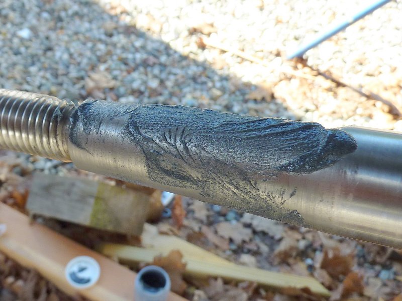


After Grinding:
Here is what it looks like after rotating and before wiping the valve grinding compound off the shaft. The picture with the compound wiped off came out all blurry so I'll need to take another one at some point.

The shaft and inside of the prop should look evenly ground with no spots that have not been honed.


The shaft and inside of the prop should look evenly ground with no high/low spots or rings that have not been honed. It should be noted that the prop is the part that will give up more material as it is significantly softer than most shafting unless you have an old bronze shaft.


High / Low Spots:

In this photo you can see a couple of either high or low spots about half way down the inside of the prop & the concentric "rings" I was talking about. This prop was worse before I started but the shots down through the bore never came out good enough to publish (note to self remember to bring flash!) This photo was only after about five rotations. I spun it a total of 22 rotations and these high/low spots were no longer visible making for a much better fit interface.


Clean The Prop & Shaft:
To clean the inside of the prop I use a terry cloth towel doused in denatured alcohol. Simply pull it through the prop a few times and you will be ready to install it.
Always check the keyway and make sure all the grinding compound is out of the it as well. If you can't get it clean with a rag you can use a q-tip to clean the keyway.


Install The Propeller:
To install the propeller you'll want to follow these simple steps:

1) Slide the prop onto the shaft, without the key, until it will not move any further. It is okay to use glycerin or a light oil, but not much to slide the prop onto the shaft as this will prevent premature binding but be sure to clean this oil or lube for the final install.

2) Mark the leading edge of the prop where it meets the shaft with a fine tip Sharpie marker. This is your insert depth mark. When installed with the key, and torqued down, you should no longer see the fine point Sharpie marking. Remove prop.

3) Install the key and slide the prop over it and up the shaft. If you can't get to your mark the key is jamming the prop and needs to be readjusted or re-fit via filing or sanding of the key.

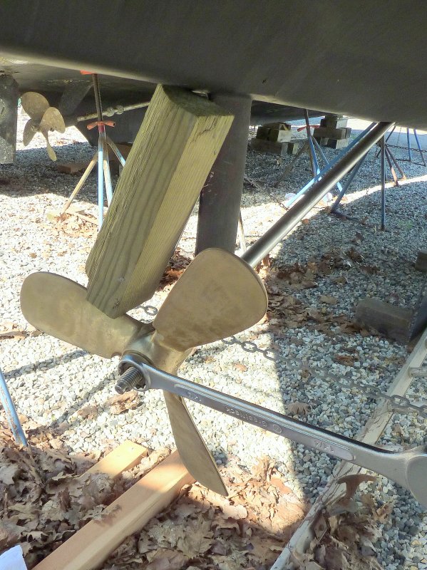
4) Thread on the big nut and insert a block of wood between the hull and prop to lock it.

5) Torque the large nut, preferably using the right sized wrench. These nuts are soft and can be rounded easily so a proper fitting wrench is a good idea. The nuts for a 1" shaft are usually, but not always, 1 1/4".

6) Once the prop has been torqued down remove the large nut and replace it with the thinner nut and torque it down.


Proper Installation of Nuts:

Yes, the small nut is supposed to go on first acting like a lock washer, with the big nut backing it up. I always torque with the big nut then flip flop them and lock them onto each other with two wrenches.

Once the nuts are on and torqued install your cotter pin. I have found that if I don't really bend over the cotter that it can hook weeds. Ideally you don't want to bend them that much, but figure out what works for your local waters.


kenn

.
Apr 18, 2009
1,271
CL Sandpiper 565 Toronto
I don't quite get why it's better to have the thin nut instead of the thick one against the prop; could you explain this? To me, it means you have to have a special thin wrench to hold the inner nut when locking the outer nut on.

Thanks.
 
Feb 6, 1998
11,672
Canadian Sailcraft 36T Casco Bay, ME
I don't quite get why it's better to have the thin nut instead of the thick one against the prop; could you explain this? To me, it means you have to have a special thin wrench to hold the inner nut when locking the outer nut on.

Thanks.
Basically it is acting like a threaded lock washer and the big nut takes the load.

This installation procedure is supported by the ABYC, SAE J755 & J756 the US Coast Guard, Michigan Wheel, the US's largest prop maker, and Dave Gerr director of Westlawn and author of the Propeller Handbook, and this is a short list.;)

You technically don't need to hold the thin nut with a wrench but I do and my 1 1/4" wrench fits fine.

Here's how the USCG directs it's folks to install the nuts:

"The propeller should be driven up the shaft taper with the large nut and torqued. The large nut is then taken off and the thin nut installed and torqued. The final step is to install the large nut again which, when torqued, unloads the thin but and bears most of the load. Notice that in this proper configuration, the thin nut still performs the locking function but acts more like a washer in transferring the force from the large nut to the propeller."

I can't say it any better than the USCG..;)
 
Dec 2, 2003
1,637
Hunter 376 Warsash, England --
Not So Sure

Maine,
The original machining tolerances should enable a satisfactory fit without need for grinding in and certainly trueness and balance should be unaffected.
Unless you have an amateur prop or shaft job the tapers should already be to the relevant standards which guarantee a correct fit.

Also I would be wary of grinding the surface of my prop shaft as it would then not be a correct fit for any subsequent prop and I would not want a depressed area where the old prop sat on the shaft.
I even delude myself with the hope that having a microscopic gap between the prop and shaft will allow enough water circulation to prevent the shaft suffering concentrated cell corrosion, otherwise known as crevice corrosion and being corroded away through lack of oxygen.
 
Feb 6, 1998
11,672
Canadian Sailcraft 36T Casco Bay, ME
Maine,
The original machining tolerances should enable a satisfactory fit without need for grinding in and certainly trueness and balance should be unaffected.
Unless you have an amateur prop or shaft job the tapers should already be to the relevant standards which guarantee a correct fit.

Also I would be wary of grinding the surface of my prop shaft as it would then not be a correct fit for any subsequent prop and I would not want a depressed area where the old prop sat on the shaft.
I even delude myself with the hope that having a microscopic gap between the prop and shaft will allow enough water circulation to prevent the shaft suffering concentrated cell corrosion, otherwise known as crevice corrosion and being corroded away through lack of oxygen.
This was taught to me by my prop shop and suggested when I purchased a new propeller to install on an old shaft. If you'd seen some of the mismatches I have lapped you'd realize that "standards" do not always make for the best fit.

As always I would advise that you do what makes you feel comfortable for your own piece of mind.

I quote Steve D'antonio one of the most respected marine consultants in the US and writer for Professional Boat Builder.

"Propeller shaft tapers require more than just cleaning, particularly for first time installations; they must be blued and lapped to remove irregularities in the typically softer propeller alloy rather than the shaft. The lapping process ensures the fullest possible taper engagement."
 

kenn

.
Apr 18, 2009
1,271
CL Sandpiper 565 Toronto
Basically it is acting like a threaded lock washer and the big nut takes the load.
...

Here's how the USCG directs it's folks to install the nuts:

"The propeller should be driven up the shaft taper with the large nut and torqued. The large nut is then taken off and the thin nut installed and torqued. The final step is to install the large nut again which, when torqued, unloads the thin but and bears most of the load. Notice that in this proper configuration, the thin nut still performs the locking function but acts more like a washer in transferring the force from the large nut to the propeller."
Well OK... but my inner 10 yr old and the shade-tree mechanic side of me both still say "whatsa diff?"

(Ok that was mostly the 10 yr old)

Would it really make that much of a difference? Under what situations would leaving the big nut torqued and locking it with the thin one fail sooner?

(Thanks for your patience. It's messy but this is how I learn.)
 
Feb 6, 1998
11,672
Canadian Sailcraft 36T Casco Bay, ME
Well OK... but my inner 10 yr old and the shade-tree mechanic side of me both still say "whatsa diff?"

(Ok that was mostly the 10 yr old)

Would it really make that much of a difference? Under what situations would leaving the big nut torqued and locking it with the thin one fail sooner?

(Thanks for your patience. It's messy but this is how I learn.)
Probably 99.8% of the time there won't ever be a problem and perhaps 50% of the prop nuts out there are installed backwards and doing fine. I would not change it unless you remove the prop for some reason. At that point then put them on using the preferred configuration. There is a right and a wrong way but the wrong way still works quite well..;) I just won't post the wrong way when I know there is a right way.....:)
 
Nov 6, 2006
9,893
Hunter 34 Mandeville Louisiana
Some quick notes on this .. Maine is correct.. The tapers will have been cut on two different machines and they will not be the same.. Close, but not the same (talking thousandths and half thousandths and tenths of thousandths).. lapping is the best way to get a great fit .. When a new prop is ground in, it will be the one to sacrifice most of the metal because it is so much softer than a typical shaft, as Maine says.. Any new prop added later will not have the same taper as the old one nor the shaft, and it will need to be ground in as well.. The concept of the fit is that when done correctly, the nuts and cotter will not even be necessary..(but yes, desirable) The prop hub stretches over the taper when the big nut is torqued, and its friction fit, when done right, will be enough to drive the prop and keep it in place. Obviously the prop will work without lapping and usually there is no problem but you’d be relying on a second back-up to hold it in place. example is a drive gear for a diesel/electric locomotive. (lots of other big machines too) The electric motor pinions are typically shrunk fit on a taper with no retainer or keyway.. they transmit lots of horsepower that reverses often .. pretty tough service compared to a prop whose delivery is into a “soft” medium.
 
May 11, 2005
3,431
Seidelman S37 Slidell, La.
Good Info Maine

Have done this for many years. First learned this trick many years ago when racing motorcycles. The flywheels would have a tendancy to spin on the shaft under racing conditions. A few minutes spent lapping with the same valve grinding compound would cure this problem. You just keep on giving good info and advice.
 
Mar 13, 2009
158
irwin 37 (73-74) grand harbor marina
made many a propshaft in my day's. the standard is 3/4" per foot. each time the lathe taper attachment is moved there's room for error. it should be checked with a dial indicator between the saddle and the ways before cutting. no reason for the shaft to leave the lathe with tool marks on the taper. keyways are better cut with a key cutter than an endmill. insist on quality work. machinist are a strange breed of cat and would and would respect your attention to detail. jimbob
 
Jan 27, 2008
3,045
ODay 35 Beaufort, NC
Now There You Go Again

Whaddayah mean "Machinists are a strange breed of cat..."? Some of my best friends and favorite people are machinists. Next to farming it is the most noblest of professions and the people in machining are the salt of the earth. If our government and society no longer value it and want it all done in foreign lands then I pity the day they need a good toolmaker to come to their rescue.
Any way here is some advice for lapping, I used to run a shop lapping fuel valves to 50 millionths roundness and straightness and diametral fits of .0001 to .0003 that had to slide freely by their own weight when wet with jet fuel. Now a human hair is about .003 in diameter so the numbers I quoted are very small.Note : all numbers in inches.
Removal of the lapping compound poses a very real problem and especially in a soft material like bronze. There are many grades of compound and many grit sizes. The grit will want to embed itself in the material and removal can be difficult. Solvents like alcohol or acetone or MEK or a stoddard safety cleaner will remove most of the grease or oil but some of the grit will still be in the material. Freon was a great cleaner but is now banned for most uses. Liquid CO2 is one of the best but try to find some. Suggest you use a clean piece of white paper after you think it is clean and rub the bore and shaft a bit. You might be surprised at what is still there. Using a pressure nozzle to flush out the compound is a good idea, something like a pressure washer. Don't do this with solvents unless you have an explosion proof set up, most solvents are highly flammable. The stoddard safety cleaner is relatively benign compared to other solvents, you can get most of it off but the embedded stuff will remain. A gun brush or other mechanical means like a scotchbrite pad may help to remove residual compound.
As for machining a perfect fit, no possible. No matter how much (or little) error two tapers will either contact on one end or the other and only the elastic deformation of the material under the torque load of the installation will bring them into contact if at all. Lapping is definitely the way to go. As for no tool marks on a lathe, I'm sure if you looked under a scanning electron microscope you would be very surprised what you see. . Tool mark depth (peaks and valleys) is typically measured as surface roughness with a lathe finish in the 63 microfinish range for rough turning, and 32 for fine work. A good machininst with a sharp tool; with a larger tip radius might get a 16 finish on a lathe but you still have peaks and valleys. A surface finish analyzer shows this very clearly. The finish is easy to calculate by the tip radius of the tool and the feed rate (inches per revolution) of the tool. The small cusp caused by the tool overlap with each turn is unavoidable but can be engineered into the job. Finer finishes require grinding and or lapping. I have seen beautiful finishes on lathes when hard turning of materials in the HRc 60 range. They can look like ground finishes but a surface analyzer will still show the peaks and valleys.
So make sure you get the compound out. It will keep working on the shaft with the relative motion between the twwo parts until after maybe 50,000 hours of motoring around you will have a problem.:eek:
 
Nov 6, 2006
9,893
Hunter 34 Mandeville Louisiana
Uhhhhh Jimbob's point taken :~)
I think it comes from considering things that normal people can't see and never think about! Its like herding cats; only a very few people can do it, most people haven't seen it, and almost all people never think about it!
 
Dec 25, 2008
1,580
catalina 310 Elk River
This is all so ridicules, we are talking about tolerances that would never be in play @ 3K RPM max. The beginnings of barnacle formation will unbalance the prop far more than what is being portrayed here. I'm sorry I just don't see the significance of creating a fit with the tolerances that is being suggested in this environment.
 
Dec 2, 2003
1,637
Hunter 376 Warsash, England --
Hey Guys,
I agree with everything said by everyone above. It is perfection - but to what effect? Increasing the contact area does not confer any more friction between shaft and prop and the key is there for that reason anyway.
Also the balance is hardly improved and the prop is unlikely to be that perfect anyway.

And yes the flywheel on a racing engine is an altogether different ball game. Presumably weighing more than a prop and turning faster then 1200 rpm
 
Nov 6, 2006
9,893
Hunter 34 Mandeville Louisiana
Not a question of balance or friction.. The trouble can happen when the torque from the nut can’t overcome a small divot and the prop hangs up on that and may not be fully seated.. A mis-matched tapeer will result in a line of contact instead of teh whole taper contacting.. After a while, the divot or thin line frets away and the prop will get loose which then frets away more of the taper fit and the prop begins to get loose.. It then starts being driven by the key and soon that will fail.. leaving the prop to spin on the shaft.. If you inspect every year when on the hard, probably won’t ever come to that.. Not a high probability, granted, but that is why ya want the tapers to be pretty tight and matched and clean.. Doesn’t have to be, it just is better that way
 
May 11, 2005
3,431
Seidelman S37 Slidell, La.
Sorry but

Anyone who thinks that only a key is needed to keep the prop from spinning on the shaft is in for a very rude awakening. The key will not keep the prop from spinning. Not for long. Even if were only talking 1200 RPM, and 30 hp or less, that little key will NOT last for long. Matter of fact, since the prop does not have to be indexed to the shaft, not even sure why the key is there.
 

Ross

.
Jun 15, 2004
14,693
Islander/Wayfairer 30 sail number 25 Perryville,Md.
Re: Sorry but

Almost all drive and driven shaft pulleys and gears are keyed and secured with set screws. I believe that the taper on the propeller shaft is standard Jacobs taper and the prop hole is reamed to size. The Jacobs taper is the same as is used in the tail stock on a lathe and it suppots and holds a drill chuck very securely.
Most shaft attchments are on straight shafts and are a tight slidding fit.
We had a boat at our marina hauled at the end of the season misssing the nuts and the end of the prop shaft but the prop was completely secure.
 
Feb 6, 1998
11,672
Canadian Sailcraft 36T Casco Bay, ME
The Jacobs taper is the same as is used in the tail stock on a lathe and it suppots and holds a drill chuck very securely.
Funny you mention this. About 15 years ago my Delta drill press kept throwing the chuck. I called Delta and the fix suggested was simple, valve grinding compound. It has been fifteen years since I fit the chuck to the drill press shaft, with valve grinding compound, and the chuck has never given me an ounce of issue since. There are no set screws or nuts holding the chuck onto my drill press.

Witz,

To call lap fitting ridiculous is calling the entire prop shafting industry ridiculous if that is your intent fine but this post is 100% in-line with industry practices. When you have seen a prop not fit all the way onto a shaft, as I have, because of irregularities between the two mating surfaces, you can and will get vibrations and as others have said can and could loose a prop.

As I have said before if you don't like it don't do it on your vessel.
 
May 11, 2005
3,431
Seidelman S37 Slidell, La.
I don't want to get political, BUT

Witz, I had to be the bearer of bad tidings, but if you are trying to relate anything in the real world with stuff that is mil spec, they you have a lot to learn. Anything that has gummit regulations attached is so, well, just screwed up, it's resemblance to the real world is lost. Many long years ago I owned a small company that manufactured motorcycle accessories. Our first products were aimed at off road and racing bikes, so federal regs were ignored. Then decided to make windshields for the Japanese bikes which were taking over the market at that time, and not much was available for them. So, the research started. Soon learned that we had to meet DOT requirements, and these requirements, for a motorcycle windshield were like 30 single spaced pages. The project was forgotten about. This is part of the reason we have 300 dollar hammers and 1000 dollar toilet seats.
 
Sep 15, 2009
6,243
S2 9.2a Fairhope Al
Funny you mention this. About 15 years ago my Delta drill press kept throwing the chuck. I called Delta and the fix suggested was simple, valve grinding compound. It has been fifteen years since I fit the chuck to the drill press shaft, with valve grinding compound, and the chuck has never given me an ounce of issue since. There are no set screws or nuts holding the chuck onto my drill press.

.
if memory serves me correctly when i was in machine shop school at Wm. R. Moore school in memphis back in the 60's the taper was called a marine taper and it was 6 degress as i recall .....

regards

woody