Hunter 34 owners
- Thread starter jk kudera
- Start date

 I drilled a hole in the guard and fed wire down the tube into the covered place in the aft cabin ceiling.
Thought I had a picture but I have nothing useful. Previous owner had run a power wire up through the pedestal tube and out a small hole in the pedestal tube. He had secured it under the clip that holds the shift and throttle cables in order to keep it out of the moving steering wires. I had to drill the fiberglass under the guard base to get the cable out.. I angled the drill bit into the guard to get the wire to go down.. I put a drip loop in the cable to keep water out of the pedestal guard.
Last edited:

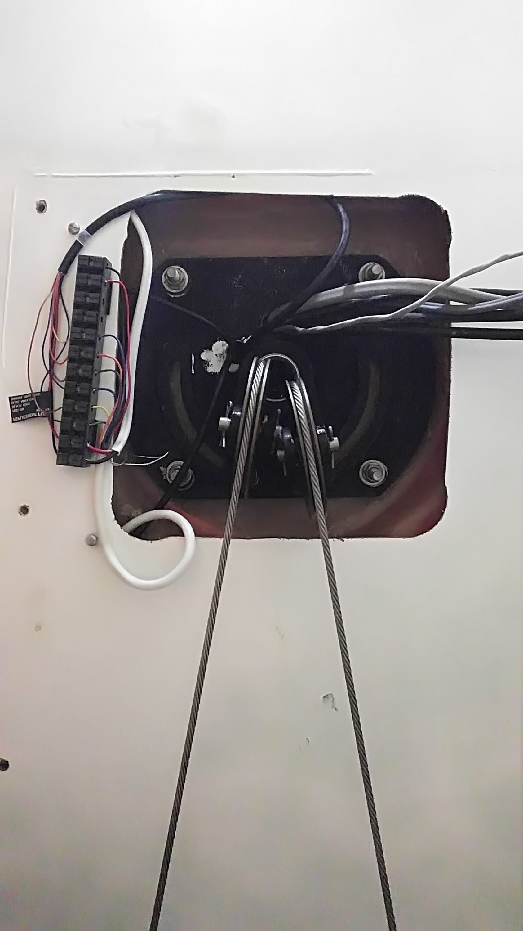
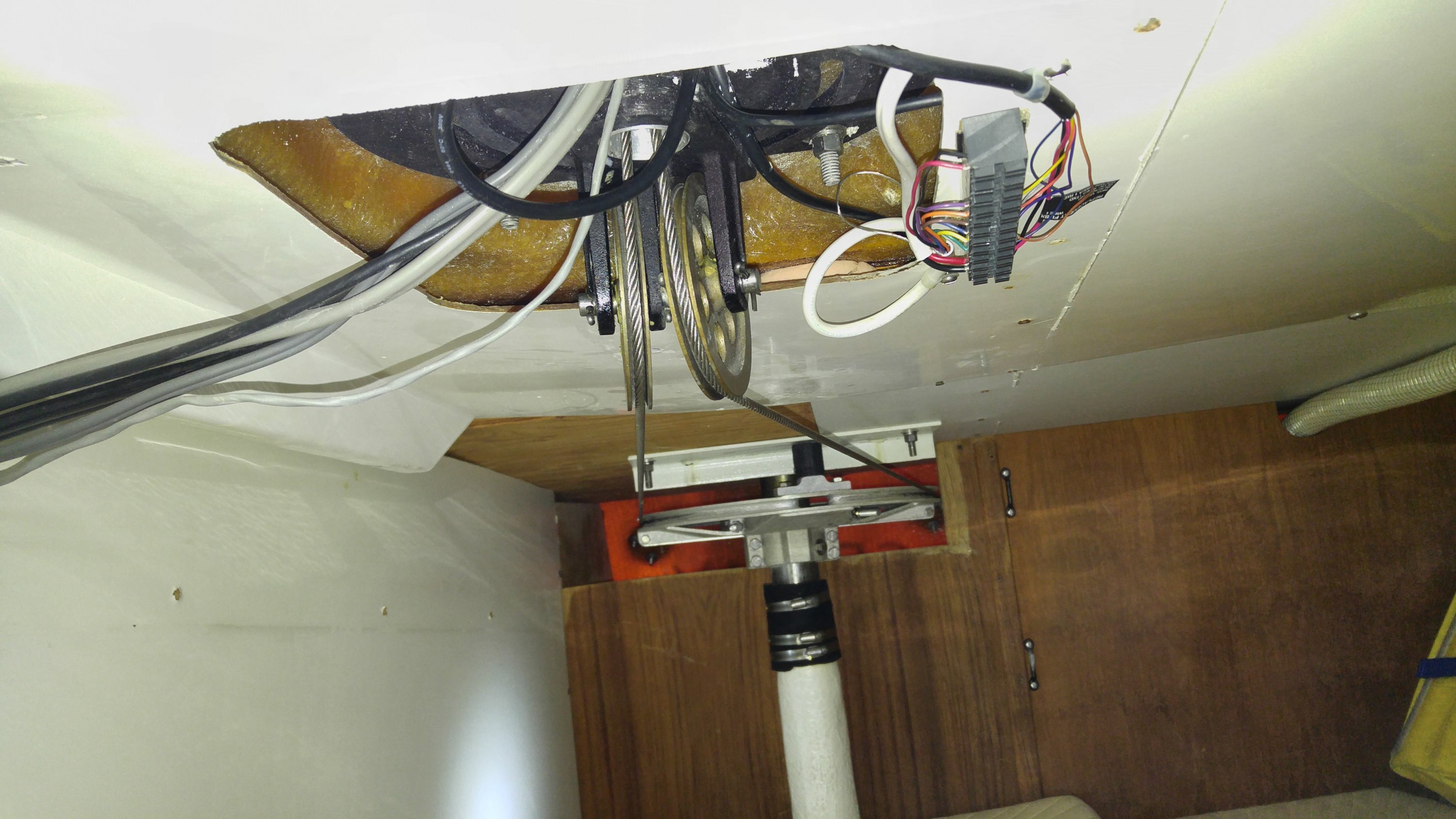
Just like Kloudie1 (Claude) I too drilled a new hole in the bottom of the pedestal. In fact I think I got the idea from him. You can use a hole saw or a spade bit to drill through the aluminum (at least 3/4" in diamater). Watch out because all the aluminum cuttings falls right into your face (and eyes). Have a vacuum handy. The tail on the supplied Garmin plotter was long enough to go all the way from the binnacle down and through the hole. I used double stick foam tape and stuck a terminal block underneath. All the wires (from the black Garmin cable) are inserted in one side. Next is the fun part. Two white cables were required. One was a pair of 16 gauge to supply the power and ground to the unit. That was specified in the instructions. The second was an 8 conductor, 20 gauge bundle for all the other inputs and outputs. I was able to fish them between the fiberglass skin of the aft berth and emerge somewhere near the hanging locker. Then route inside the locker and drill a hole in the wood bulkhead into the interior of the circuit breaker panel. I only used the NEMA 0183 connections. So I had AIS out of my B&G to the Garmin. GPS out from the Garmin went to the B&G and split back to my Raymarine Autopilot. I've attached my crude schematic ( .pdf file below) with the wire colors (naturally the cable from West Marine didn't use the same colors as the Garmin at one end and the B&G at the other). I used another smaller terminal strip behind the circuit breaker panel just to keep things organized. Note that I also split the outgoing AIS signal from the radio and have that go to a DB-9 serial plug then a USB/serial adapter cable. I used to use a laptop and run Open CPN software so I could see charts and AIS at the nav station. Later I got a Raspberry PI computer and with the same software I output it to my 15" LED 12V TV. It's like a giant chart plotter down below. That's been pretty cool too.
For the 9 feet or so separation between the bottom of the pedestal to the circuit breaker panel I needed 25 feet of the cables. You know the saying "you can't get there from here" is never truer. Have fun snaking wire.
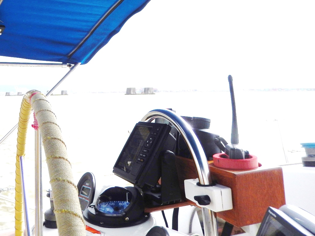
Regarding mounting the Garmin 547, I used a teak binocular and cup holder that I bought at West Marine. An additional piece of teak is screwed to the bottom and a half circle is cut to follow the contour of the compass for support. Hope you can see that in the picture. The GPS mount is screwed to that. It works well as I disconnect the cable at the back (I don't use a fishfinder transducer) and open the binnacle clamps to remove the entire thing when we go home. I actually take the GPS off its mount and bring it home. I bought an extra cable on Amazon so I can power it up with the right connector and review tracks or play with the SD card either preloading routes, waypoints and such using the Garmin software on my computer. Very nice for voyage preparation. Although I will say, I liked the old Garmin interfaces better with the Page and Quit key. I could upload detailed tracks via USB to my laptops much easier. The new menu driven interface has not been intuitive to me and I don't get the file storage formats. Maybe it's just me.
I hope this helps.
For the 9 feet or so separation between the bottom of the pedestal to the circuit breaker panel I needed 25 feet of the cables. You know the saying "you can't get there from here" is never truer. Have fun snaking wire.
Regarding mounting the Garmin 547, I used a teak binocular and cup holder that I bought at West Marine. An additional piece of teak is screwed to the bottom and a half circle is cut to follow the contour of the compass for support. Hope you can see that in the picture. The GPS mount is screwed to that. It works well as I disconnect the cable at the back (I don't use a fishfinder transducer) and open the binnacle clamps to remove the entire thing when we go home. I actually take the GPS off its mount and bring it home. I bought an extra cable on Amazon so I can power it up with the right connector and review tracks or play with the SD card either preloading routes, waypoints and such using the Garmin software on my computer. Very nice for voyage preparation. Although I will say, I liked the old Garmin interfaces better with the Page and Quit key. I could upload detailed tracks via USB to my laptops much easier. The new menu driven interface has not been intuitive to me and I don't get the file storage formats. Maybe it's just me.
I hope this helps.
Attachments
-
113.1 KB Views: 131
Allen's wire run is great! I would do the wire the way he ran it looks clean and accessible.
As far as mounting the unit Defender has gps mounting hardware and kits that are a bit expensive. I used a nylon rail mount antenna base and a small piece of starboard and a two bolts and two washers.
Drilled hole thru the starboard to allow the antenna base threads to pass thru. Threaded a bolt with over sized washer onto threads of the antenna base, placed starboard onto bolt and washer, thread another washer and bolt onto the starboard, and tighten. Now you can mount the gps bracket onto the starboard. Instant gps mount for about $15 bucks compared to $190 stainless steel gps mount from defender.
I'm totally in the wrong business, just slap a marine sticker on it and you can charge people whatever you want. Marine industry what a bunch of thieves
I will try to snap a pic next week when I go back to the boat.
I have a very similar pedestal.

Below are pics of what I did for my Raymarine C80. I still have not routed the wiring since I am searching for a raystar 125 GPS module first. However, I am planing on adding a new waterproof thru-deck fitting next to the Binnacle guard rail.


Below are pics of what I did for my Raymarine C80. I still have not routed the wiring since I am searching for a raystar 125 GPS module first. However, I am planing on adding a new waterproof thru-deck fitting next to the Binnacle guard rail.

Is that a 125 or a 150?Pateco,
Is this what you are looking for.
I am pretty sure it is a 125. It is up in the attic right now. I will double check tomorrow morning. I replaced my electronics last year and kept the things that were working.
Pateco,
The book says Raystar 120. It was connected to an RL70C Pathfinder series chart plotter.
Butch
The book says Raystar 120. It was connected to an RL70C Pathfinder series chart plotter.
Butch
Any Idea what you would want for it?Pateco,
The book says Raystar 120. It was connected to an RL70C Pathfinder series chart plotter.
Butch