Sounds like I should move the charger upgrade up on my priority list. Especially when I am using much better batteries than planned.
Absolutely!
I was planning on the Sterling Pro Charge Ultra 20A charger. Will I need to bump it up to 30A for the 230Ah bank? I will be charging overnight so speed of charge isn’t a requirement.
I like the 30A unit much better due to the output studs actually being studs rather than a dinky little terminal strip. At
$275.00 for a 30A charger with temp sensor this is a very hard charger to beat price wise.
Do you mean forward under the settee or aft under the nav station?
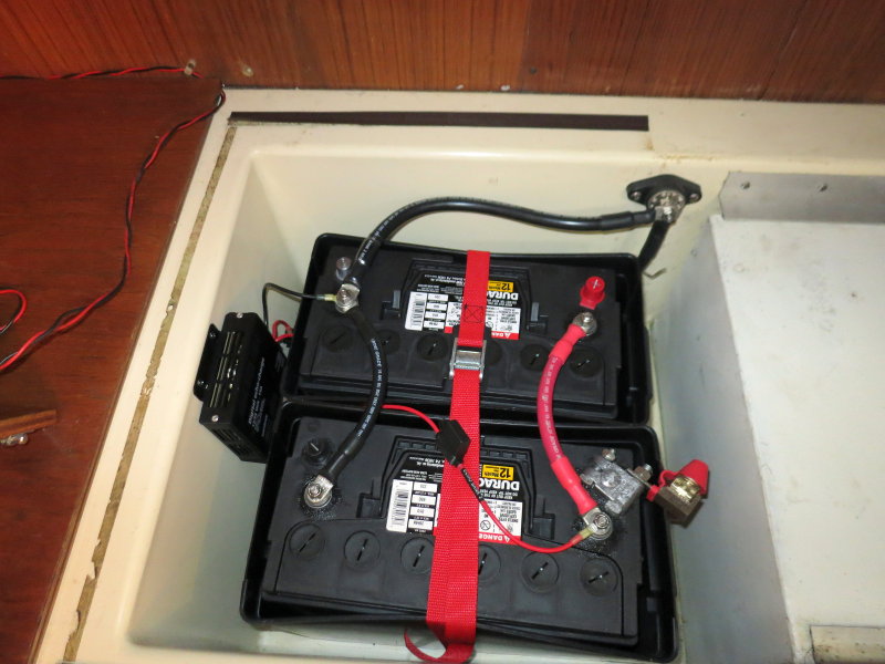
Depends upon the boat, I have done it three ways. If you do under the nav table then a teak cover would need to be built, pretty easy though. Often most of this stuff will fit right in the battery compartment as the GC2's leave room. If you ensure that fiberglass compartment is
sealed, no holes/screws etc. in the bottom, that will satisfy the battery case/acid containment, issue.
That’s the plan. The battery selector switch will be a “Use” switch. House bank for all power needs. The aux bank will only be used if the house bank fails.
Which is why I was planning on using the Blue Sea #7601 m-Series ACR which is rated at 65Amps.
Why more than double the amp rating of my largest charge source?
For the few dollars more (about $20-25 more) the 7610SI is really a better mouse trap. Dual 3/8" studs vs. 1/4" studs, can even hold an MRBF. I will often do this and place the ACR within 7" of the battery when height is an issue, and use one MRBF to satisfy the ABYC requirement for the house bank over current protection. You're not mounting an MRBF on a dinky little 1/4" stud. The 3/8" terminals on the 7610SI can also work as a bus point for chargers alternators etc... The 7610SI also features SI or start isolation which can be used if or when you decide to make your start battery an actual
isolated start bank. The 7610SI is also proven and they are absolutely bullet proof. They even survive stater in-rush when wired incorrectly. The 65A unit is okay, and will work, but for the $20.00 more the 7610SI really makes the 65A model a non-starter for me....
I thought the ACR only combined the batteries during charging after the house bank is fully charged.
Nope not at all.. I don't have time to hit all the points or confusion of ACR's but perhaps can cover a few of them.
The ACR or a VSR or a Combiner are very simple devices yet they myths and misinformation that surround them are endless.
What is an
ACR? Simple...
A
VOLTAGE ACTIVATED & DEACTIVATED
BOTH/PARALLEL SWITCH
or
Automatic Combining Relay
or
Automatic Paralleling Switch
or
Voltage Sensing Relay
or
Combiner (Paralleler)
The term RELAY is just a fancy word for SWITCH
Blue Sea ACR Myths & Misunderstandings
#1 "I don't want a device that can drain my start battery into the house battery." - Myth = False..
The combine/parallel voltages of the Blue Sea ACR are
above the full charge resting voltage of a 12V battery. With 13.0V (combine low) or 13.6V (combine high) applied to the battery terminals current can only flow
INTO the banks, not out of the banks.
The Blue Sea ACR will combine / parallel the banks at 13.0V after 90 seconds or 13.6V after 30 seconds. Any time the battery terminal voltage is
above the batteries SOC voltage,
current can only flow in one direction, and that is
into the battery. The ACR
combine voltage set points are
ABOVE the voltage of a fully charged lead acid battery..
The idea that a start battery or house battery can drain into one another, with an ACR, is not possible other than for 10 seconds or 30 seconds maximum. It takes voltage differentials to move current between batteries and the the energy that can move between the batteries in 10 seconds at 12.35V (open low) or 30 seconds at 12.75V (open high) is beyond minuscule.
#2 "I like that it fully charges my XXXXX bank first, then charges the other bank." - Myth = False
This is how an ACR works;
Charge Source ON
>Alternator or other charge source is turned ON
>Battery receiving charge current comes up to 13.0V
>90 Seconds after attaining 13.0V the relay closes & parallels the two banks
> If voltage is rising quickly paralleling takes only 30 seconds at 13.6V
>Batteries remain in parallel until charging is discontinued
You simply can not charge any lead acid battery, even a start battery, in the 30 or 90 seconds time it takes the relay to parallel the banks at 13.0V or 13.6V. Beyond just the 30 or 90 second time constraints, you simply can't charge any lead acid battery to
full at 13.0V or 13.6V.
Charge Source OFF
>Alternator or other charge source is turned OFF
>Bank voltage falls/decays back below 12.75V
>After 30 seconds at or below 12.75V the relay opens isolating the two banks.
>If a heavy load is applied (inverter, windlass etc.) and voltage sags to 12.35V the relay opens in 10 seconds.
The full charge voltage of most lead acid batteries is between 12.6V and 12.73V so the ACR opens before any measurable capacity can be taken from the start battery..
#3 "These devices won't last because the relay will chatter." - Myth = False..
The Blue Sea ACR's use time delay logic for both combine and un-combine to avoid "relay
chatter". Relay
cycling and relay
chatter are two different issues. If the ACR is installed
incorrectly/backwards, for the application, and the source charge current is low, the relay may open back up, with delay logic, after it has closed. It is important to understand that the Blue Sea relays CAN NOT CHATTER due to the inherent design.. For example; If you connect the charge sources to the start battery first, when it combines with house, the voltage gets sucked back below the combine level, and the relay may open. This is called "relay cycling". RElay cycling only slows house bank charging and relay "chatter" would actually damage the relay. The ACR can not chatter.
The Blue Sea ACR also monitors
voltage trends. It does this to help
minimize relay cycling. For example if battery voltage sensed at either the A or B terminal should be pulled down to 12.35V
or below, the relay logic looks at the voltage trend to determine what action to take. If it does not attain 12.35V within 10 seconds, it unparallels the banks or "opens" the relay. If it detects a voltage rise above 12.35V and then attains 12.75V within 30 seconds it will remain closed and keep the batteries in parallel. If still going down, after 12.35V or lower is detected, it will then open up fairly rapidly (within 10 seconds). If voltage is trending up but it does not attain 12.75V within 30 seconds it will open.
#4 "Charging should originate from the start battery, not house, the ACR instructions say so." - Misunderstanding = Application dependent..
Where the charge sources feed depends entirely upon the installation. Unfortunately Blue Sea is unclear about this in the instructions that come with an ACR. The instructions provided with the ACR are really intended for boats with equal sized banks such as a small center console etc., not for an actual cruising boat. For properly wiring an ACR into a cruising boat you need to dig deep into the Blue Sea tech articles to find the correct installation instructions. The article below shows the correct wiring for ACR to a deep cycling large house bank.
Blue Sea Systems Tech Article #527 - Preventing Relay Cycling
Image Courtesy Blue Sea Systems
In almost every installation,
on a cruising boat, with
disparate sized battery banks, charge source current should feed the
house bank first & not the start bank. This prevents
relay-cycling because it allows the larger house bank to attain the
combine voltage before combining with the
much smaller, and almost always nearly fully charged, start battery.
Feeding all charge sources to the house bank also results in faster charging & better voltage sense accuracy of the house bank. When you avoid
relay-cycling, the house bank charges faster. With less voltage drop between the charge source and the house battery positive terminal, that comes from not sticking a relay, multiple terminals and two more fuses it is path, the charge performance of the house bank is improved once again.
What tech article #527 does not discuss well enough is relay-cycling with
low current charge sources such as solar, wind, small shore chargers or even hydrogen fuel cells.. With low charge current the reality of properly wiring all sources to house first becomes is even more critical. If you were to wire a 50W solar panel to start first, and try to charge a large house bank at 50% DOD, it is going to take a very, very long time to get the two banks to stop relay-cycling and get sufficient energy back into the house bank in order to maintain the combine/parallel parameters. The designed delay logic can work ok for large current sources, such as alternators, but not for small current sources which can't create enough of a voltage trend..
Think about it this way, why continually pass a typical 70A to 400A+ of charging current
across the relay, plus multiple terminals, two fuses & multiples more connection points, all creating voltage drop, when you only need to pass a
few amps across the relay when it only needs to feed a near full charge and much, much smaller start or reserve bank? By feeding
house first the relay is combining with a nearly fully charged start bank that, in most cases, only needs a few amps. The voltage drop when feeding
a few amps is minimal to almost none, when compared to forcing all that charge current through the relay, terminals and fuses and then into the deeply discharged house bank.
#5 "But if I feed the house bank first my start battery will never get charged." - Myth = False..
Attaining the combine/parallel voltage, even for AGM batteries, should not take a long time provided you are actually
charging the batteries
properly (see link below
). Low current solar and wind will take slightly longer to attain combine voltage parameters (13.0V for 90 seconds) but your start battery, unless something is wrong, should already most likely be at 97-99% SOC, so a
little slower combine time, with alternative energy, still beats a batteries self discharge rate and is a
non-issue.
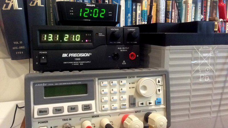
For what it is worth a number of years ago I ran an experiment with a 55HP diesel where the alternator was disabled, on purpose. This was done to figure out how many starts one could achieve off the single G-31 "
deep cycle" battery. After starting that motor 42 times, I grew tired and gave up. The next morning the resting voltage of the single G-31 "deep cycle", after starting the motor 42 times, had rebounded to a resting OCV of 12.57V..
How Fast Can an AGM Battery Be Charged (LINK)
This image has been resized. Click this bar to view the full image. The original image is sized %1%2.
Think about this snap shot if you use or are considering a battery combining relay for charge management and are concerned or have been scared off by one of the many myths surrounding these effective and reliable charge management devices.
The myth goes something like this:
By using a battery combiner, on AGM batteries, and feeding the alternator or battery chargers directly to the house battery bank
first,
"It will leave your start battery under charged".
If you are practicing good battery management, and have even the minimum suggested charge current for an AGM battery (Lifeline recommends a bare minimum of 20% of Ah capacity or .2C) this is simply a non-issue.
In just 2 minutes of charging, at .2C / 20% of Ah capacity beginning from 50% SOC, the AGM battery voltage is already at the “combine level” for a Blue Sea ACR. Once at 13.0V the relay has a delay of 90 seconds before combining/paralleling the banks. So, from 50% SOC with a .2C charge rate, it will take approx 3:30 for the relay to combine with the start battery and begin charging it. 90 seconds of this 3:30 is a built in timer delay in the ACR logic. In other words in just 2 minutes you're house bank is already at the combine/parallel level if charging at .2C with AGM batteries. Bump the charge current to .25 -.4C (where it really should be for AGM's) and the bank is attaining combine voltage almost instantly. This is whwy Blue Sea incorporates both
low (13.0V) and a
high (
13.6V) combine points, not just 13.6V like some other manufacturers do..
Battery voltage in bulk will rise pretty slowly from the low 13's on but to get to an ACR’s “
combine level” is relatively quick and easy, especially if you have your system set up properly. The Echo Charger, Duo Charger and numerous other DC to DC chargers also turn on at similar voltages and those devices require
all charge sources to be fed to the house bank in order to work properly.
#6 "If it only knows the voltage of one bank it can't know when to combine and un-combine correctly." - Myth = False..
The current Blue Sea ACR's are "
dual-sensing" meaning they sense the voltage of either bank and can combine or un-combine based on either the "A" or "B" terminal voltages and delay logic.
Only some the earliest Blue Sea ACR's (circa early 2000's) such as the CL-Link 7600 or 9112 etc., which were long ago discontinued, could be set up for single bank or dual bank sensing. Some of the earliest models only had a delay on the combine side and would not combine until 13.6V for 30 seconds, and they opened at 12.6V with no or minimal delays. Along the way Blue Sea learned a lot and totally re-vamped the product line with numerous improvements. These older models should not be compared to the significantly improved later models such as the ML-ACR or the 7610SI-ACR etc.. Current ACR's all sense both sides, hence the "dual-sensing".
#7 "My ACR can charge my house bank and then give a start battery profile to my start battery." - Myth = False..
The Blue Sea ACR's
do not provide a different
charge profile to another bank. This is another ACR
myth and I don't know where this really foolish one started? These devices are nothing more than an electronic paralleling switch that combine/parallel banks when charging voltages are present and un-combine when charging voltages are no longer present. The key word here is "parallel". Batteries in parallel are seeing the same voltages minus any slight voltage drop between the banks.
#8 "My ACR can be used as an emergency parallel to start my boat." Misunderstanding = Product specific.
Only the larger and more expensive Blue Sea
ML-ACR (ML = Magnetic Latching / relays capable of 500A continuous) can be used as a
manually activated parallel switch. The smaller ACR's such as the 7610SI or the m-ACR can not be used for
manually paralleling banks. If you have a 7610SI or an m-ACR you will need to
keep your manual paralleling battery switch.
#10 "Oh great another piece of gear and another spare to carry." - Misunderstanding - Application
In an
adequately wired & engineered cruising vessels DC system any Combiner/VSR/ACR should ideally be a
redundant charge directing or charge management device. These devices are intended to eliminate human error or human forgetfulness not to replace a solid wiring foundation.
A failure of an ACR,
no matter how rare, only means you now need to
manually parallel the banks, with your on-board manual switches. If a vessel can not
manually manage charging &
bank isolation then the system was not very well designed for cruising use to begin with.
#11 "An ACR can only charge one type of battery and you can't mix chemistries." Misunderstanding = Application specific..
Batteries charge based on a specific float or absorption voltage. They don't care how or why this voltage got to their terminals. As long as any two banks have the same or very similar charge voltages they can be charged via an ACR, regardless of bank type, eg: AGM, GEL or Flooded. The key here is not the "type" but that the
bank is seeing the correct float and absorption voltages.
An ACR just parallels banks and thus the same charge voltages are applied to each bank, because they are charging in
parallel.. This is really no different than
most all so called "
smart battery chargers" which feature multiple outputs. If the float voltage requirements are also the same, or very similar, then one charger can feed two different battery
types without issue. All batteries should be charged temp compensated.
For example an Odyssey TTPL AGM can be adequately charged at 14.7V & 13.6V and a Trojan flooded bank also be adequately charged at 14.7V & 13.6V. There is no reason an Odyssey TPPL AGM can't be charged as a start battery when the house bank is Trojan flooded.
An ACR is really not any different than a typical "
smart battery charger" that has but one charge profile hiding behind two or three outputs. Each of the outputs on a "smart battery charger" are using the
same charge profile.
While a
smart charger may have outputs for "
three-banks" it is still one charger with one single voltage setting used at a time. If voltages of different type banks play well together the banks can be charged via one smart battery charger or via an ACR.
Regardless of whether you have a multi-output charger or an ACR, you can't for example put a GEL battery that needs 14.1V on output #2 and a Trojan that needs 14.8V on output #1 and then set the charger to FLOODED because you will cook the GEL battery. If you set it to GEL then you chronically under charge the Trojan and also ruin it.The ACR is no different in this regard. It will apply the charge source voltage to the bank being charged.
#12 "I have solar and I don't want my banks in parallel while starting or brownouts & damage will occur to my electronics." - Misunderstanding = Product specific/incorrect installation.
With a dedicated start bank and alternative energy the relay may be in parallel when you want to start the motor. Unfortunately we don't want nor need the hosue bank in parallel with start if one intends on an isolated starting battery. No worries the Blue Sea SI feature comes to the rescue.
SI =
Start Isolation.
A Blue Sea 7610SI is rated at 120A continuous or 210A for 5 minutes but if wired PROPERLY, & most of them are not, the relay is physically opened/disabled during engine cranking. This feature is called SI or "start isolation". A feed from your ignition switch opens the relay, during cranking, thus avoiding passing 300A-600A+ across a 120A continuous rated relay. It also minimizes related voltage transients that can occur cranking, especially in poorly wired systems.
Unfortunately I see the SI feature, an excellent feature, grossly under utilized & largely ignored..